2-56
Service Guide
2.6
TI PCI1131 CardBus Controller
2.6.1
Overview
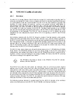
The PCI1131 is a bridge between the PCI local bus and two PC Card sockets supporting both 16-
bit and 32-bit CardBus PC Cards, and is compliant with the PCI Local Bus Specification Revision
2.1 and PCMCIA's 1995 PCI Card Standard. The PCI 1131 PC Card interface recognizes and
identifies PC Cards installed at power-up, run-time, and switches protocols automatically to
accommodate 16-bit and 32-bit cards. Support for new 1 6-bit PC Card features such as multi-
function cards, 3.3V cards, and DMA, as well as backward compatibility to the PCMCIA Release
2.1-compliant PC Cards are included in the PCI1131. CardBus cards operating at up to 33MHz
and with a 32-bit data path offer higher performance, and the PCI1131 allows applications to take
full advantage of this bandwidth. The PCI1131 core is powered at 3.3V to provide low power
dissipation, but can independently support either 3.3V or 5V signaling on the PCI and PC Card
interfaces.
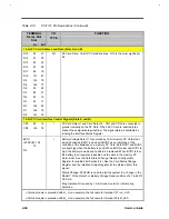
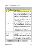
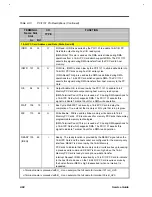
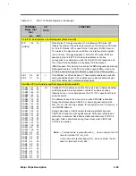
Host software interacts with the PCI1131 through a variety of internal registers which provide
status and control information about the PC Cards currently in use, and the internal operation of
the PCI1131 itself. These internal registers are accessed by application software either through the
PCI Configuration header, or through E programmable windows mapped into PCI memory or l/O
address space. The concept of windows is also user by the PCI1131 to pass cycles between PCI
and PC Card address spaces, and host software must program the location and size of these
windows when the PCI1131 or PC Card is initialized.
The PCI1131 also communicates via a three-line serial protocol to he TI TPS2206 Dual PCMCIA
Power Switch. The TPS2206 switches Vcc and Vpp supply voltage to the two PC Card sockets
independently. Host software has indirect control over the TPS2206 by writing to internal PCI1131
registers. In order to prevent damage to low-voltage CardBus PC Cards, the PCI1131 will allow
only valid Vcc settings to be applied to such cards.
The TPS2206 is the follow-on device to the TPS2202. The PCI1131 will also
interface with the TPS2202.
The PCI1131 can notify the host system via interrupts when an event occurs which requires
attention from the host. Such events are either card status change events (CSC) or functional
interrupts from a PC Card. CSC events occur within the PCI1131 or at the PC Card interface, and
indicate a change in the status of the socket (i.e., card insertion or removal). Functional interrupts
are interrupts which originate from the PC Card application itself, and are passed from the card to
the host system. Both CSC and functional interrupts may be individual masked and routed to a
variety of system interrupts. The PCI1131 can signal the system interrupt controll via PCI-style
interrupts, ISA IRQ's, or with the Serialized IRQ protocol.
The following sections describe in greater detail how the PCI1131 interacts at an electrical,
protocol, and software level at its PCI, PC Card, TPS2206, and interrupt interfaces
Summary of Contents for AcerNote Light 370P
Page 6: ...vi ...
Page 26: ...1 8 Service Guide Figure 1 5 Main Board Layout Bottom Side ...
Page 49: ...System Introduction 1 31 1 5 1 3 Power Management Figure 1 14 Power Management Block Diagram ...
Page 55: ...System Introduction 1 37 1 6 System Block Diagram Figure 1 15 System Block Diagram ...
Page 64: ...Major Chips Description 2 7 2 2 5 Pin Diagram Figure 2 4 M1521 Pin Diagram ...
Page 99: ...2 42 Service Guide 2 5 3 Pin Diagram Figure 2 10 C T 65550 Pin Diagram ...
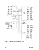
Page 117: ...2 60 Service Guide Figure 2 12 Functional block diagram CardBus Card Interface ...
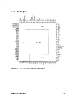
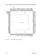
Page 119: ...2 62 Service Guide Figure 2 14 PCI to CardBus terminal assignments ...
Page 135: ...2 78 Service Guide 2 7 3 Pin Diagram Figure 2 16 NS87336VJG Pin Diagram ...
Page 145: ...2 88 Service Guide 2 8 2 Pin Diagram Figure 2 17 YMF715 Block Diagram ...
Page 185: ...Disassembly and Unit Replacement 4 5 Figure 4 3 Disassembly Sequence Flowchart ...
Page 209: ...B 2 Service Guide ...
Page 210: ...Exploded View Diagram B 3 ...

