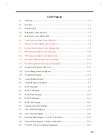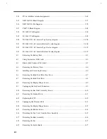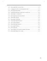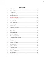
xii
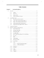
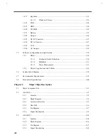
Disassembling the Inside Frame Assembly .....................................................................4-10
Removing the Heat Sink Assembly .................................................................4-10
Removing the Internal Drive ..........................................................................4-11
Replacing the CPU .........................................................................................4-12
Removing the Display ....................................................................................4-13
Detaching the Top Cover................................................................................4-14
Removing the Base Assembly .........................................................................4-16
Removing the Motherboard ............................................................................4-17
Disassembling the Motherboard......................................................................4-20
Removing the Touchpad .................................................................................4-21
Disassembling the Display..............................................................................................4-22
Appendix F
Technical Bulletins and Updates
Appendix G
Forms
Summary of Contents for AcerNote Light 370P
Page 6: ...vi ...
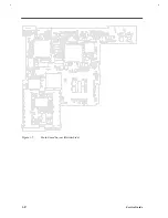
Page 26: ...1 8 Service Guide Figure 1 5 Main Board Layout Bottom Side ...
Page 49: ...System Introduction 1 31 1 5 1 3 Power Management Figure 1 14 Power Management Block Diagram ...
Page 55: ...System Introduction 1 37 1 6 System Block Diagram Figure 1 15 System Block Diagram ...
Page 64: ...Major Chips Description 2 7 2 2 5 Pin Diagram Figure 2 4 M1521 Pin Diagram ...
Page 99: ...2 42 Service Guide 2 5 3 Pin Diagram Figure 2 10 C T 65550 Pin Diagram ...
Page 117: ...2 60 Service Guide Figure 2 12 Functional block diagram CardBus Card Interface ...
Page 119: ...2 62 Service Guide Figure 2 14 PCI to CardBus terminal assignments ...
Page 135: ...2 78 Service Guide 2 7 3 Pin Diagram Figure 2 16 NS87336VJG Pin Diagram ...
Page 145: ...2 88 Service Guide 2 8 2 Pin Diagram Figure 2 17 YMF715 Block Diagram ...
Page 185: ...Disassembly and Unit Replacement 4 5 Figure 4 3 Disassembly Sequence Flowchart ...
Page 209: ...B 2 Service Guide ...
Page 210: ...Exploded View Diagram B 3 ...


