2-64
Service Guide
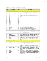
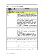
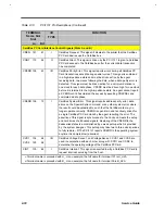
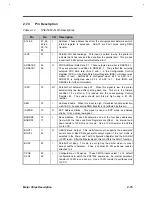
Table 2-13
PCI1131 Pin Descriptions (Continued)
TERMINAL
NAME NO.
I/O
TYPE
FUNCTION
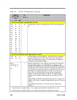
PCI Address and Data Terminals
C/BE3 180
C/BE2 192
C/BE1 203
C/BE0 5
I/O
8us commands and byte enables. These are muitiplexed on the same
PCI terminals. During the address phase, C/BE-0 define the bus
command. During the data phase, C /ENEW-O are used as byte
enables. The byte enables determine which byte lanes carry
meaningful data. C/BE0 applies to byte 0 (AD7-0), C/BE1 applies to
byte 1 (AD15-8), C/BE2 applies to byte 2 (AD23-16),and C/BE3
applies to byte 3 (AD31-24).
PAR 202
I/O
Parity. As a PCI target during PCI read cycles, or as PCI bus master
during PCI write cycles, the PCI 1131 calculates even parity across the
AD and C/BE buses and outputs the results on PAR, delayed by one
clock.
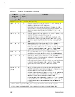
PCI Interface Control Terminals
DEVSEL 197
I/O
Device select. As a PCI target, the PCI1131 asserts DEVSEL to claim
the current cycle. As a PCI master, the PCI1131 monitors this signal
until a target responds or a time out occurs.
FFAME 193
Cycle frame. Driven by the current master to indicate the beginning
and duration of an access, FRAME I/O is low (asserted) to indicate
that a bus transaction is beginning. While FFGI9IE is asserted, data
transfers continue. When FRAME is sampled high (deasserted), the
transaction is in the final data phase .
GNT 168
I
Grant. Driven by the PCI arbiter to grant the PCI1131 access to the
PCI bus after the current data transaction has completed.
IDSEL 182
I
Initialization device select. IDSEL selects the PCI1t31 during
configuration accesses. IDSEL can be connected to one of the upper
24 PCI address lines.
IRDY 195
I/O
Initiator ready. IRDY indicates the bus master's ability to complete the
current data phase of the transaction. IRDY is used in conjunction with
IRDY. A data phase is completed on any clock where I/O both IRDY
and TRDY are sampled low (asserted). During a write, IRDY indicates
that valid data is present on AD31-0. During a read, IRDY indicates
that the master is prepared to accept data. Wait cycles are inserted
until both IRDY and TRDY are low (asserted) at the same time. This
signal is an output when the PCI1131 is the PCI bos master and an
input when the PCI bus target.
STOP 198
I/O
Stop. This signal is driven by the current PCI target to request the
master to stop the current transaction.
PERR 99
I/O
Parity error. This signal is driven by the PCI target during a write to
indicate that a data parity error has . been detected.
REQ 169
O
Request. Asserted by the PCI1131 to request access to the PCI bus as
a master.
SERR 200
O
O System error. Output pulsed from the PCI1131 indicating an
address parity error has occurred.
Summary of Contents for AcerNote Light 370P
Page 6: ...vi ...
Page 26: ...1 8 Service Guide Figure 1 5 Main Board Layout Bottom Side ...
Page 49: ...System Introduction 1 31 1 5 1 3 Power Management Figure 1 14 Power Management Block Diagram ...
Page 55: ...System Introduction 1 37 1 6 System Block Diagram Figure 1 15 System Block Diagram ...
Page 64: ...Major Chips Description 2 7 2 2 5 Pin Diagram Figure 2 4 M1521 Pin Diagram ...
Page 99: ...2 42 Service Guide 2 5 3 Pin Diagram Figure 2 10 C T 65550 Pin Diagram ...
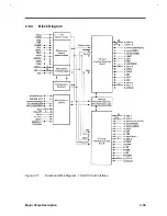
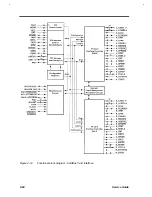
Page 117: ...2 60 Service Guide Figure 2 12 Functional block diagram CardBus Card Interface ...
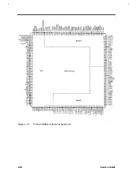
Page 119: ...2 62 Service Guide Figure 2 14 PCI to CardBus terminal assignments ...
Page 135: ...2 78 Service Guide 2 7 3 Pin Diagram Figure 2 16 NS87336VJG Pin Diagram ...
Page 145: ...2 88 Service Guide 2 8 2 Pin Diagram Figure 2 17 YMF715 Block Diagram ...
Page 185: ...Disassembly and Unit Replacement 4 5 Figure 4 3 Disassembly Sequence Flowchart ...
Page 209: ...B 2 Service Guide ...
Page 210: ...Exploded View Diagram B 3 ...


