2-68
Service Guide
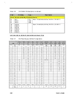
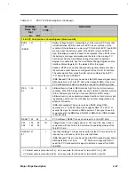
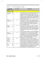
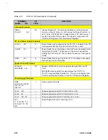
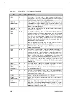
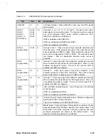
Table 2-13
PCI1131 Pin Descriptions (Continued)
TERMINAL
Name Slot
Slot
I/O
TYPE
FUNCTION
A+ B
≠≠
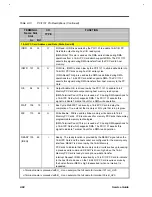
1 6-bit PC Card Address and Data (Slots A and B)
IORD
99 33
O
I/O Read. LORD is asserted by the PCI1131 to enable 16-bit l/O PC
Card data output during host I/O read cycles.
(DMA Write) This pin is used as the DMA write strobe during DMA
operations from a 16-bit PC Card which supports DMA. The PCI 1131
asserts this signal during DMA transfers from the PC Card to host
memory.
IOWR
101 35
O
I/O Write. IOWR is driven low by the PCI1131 to strobe write data into
16-bit l/O PC Cards during host I/O write cycles.
(DMA Read) This pin is used as the DMA read strobe during DMA
operations to a 16-bit PC Card which supports DMA. The PCI 1131
asserts this signal during DMA transfers from host memory to the PC
Card.
OE
98 32
O
Output Enable. OE is driven low by the PCI 1131 to enable 16-bit
Memory PC Card data output during host memory read cycles.
(DMA Terminal Count) This pin is used as TC during DMA operations to
a 16-bit PC Card which supports DMA. The PCI 1131 asserts this
signal to indicate Terminal Count for a DMA write operation .
WAIT
136 70
I
Bus Cycle Wait. WET is driven by a 16-bit PC Card to delay the
completion of (i e. extend) the memory or l/O cycle that is in progress.
WE
110 46
O
Write Enable . WE is used to strobe memory write data into 16-bit
Memory PC Cards. VVE is also used for memory PC Cards that employ
programmable memory technologies.
(DMA Terminal Count) This pin is used as TC during DMA operations to
a 16-bit PC Card which supports DMA. The PCI 1131 asserts this
signal to indicate Terminal Count for a DMA read operation.
READY 135 69
(IREQ)
I
Ready . The ready function is provided by the READY signal when the
16-bit PC Card and the host socket are configured for the memory-only
interface. READY is driven low by the 16-bit Memory
PC Cards to indicate that the memory card circuits are busy processing
a previous write command. READY is driven high when the 16-bit
Memory PC Card is ready to accept a new data transfer.
Interrupt Request. IREQ is asserted by a 16-bit I/O PC Card to indicate
to the host that a device on the 16-bit I/O PC Card requires service by
the host software. IREQ is high (deasserted) when no interrupt is
requested.
+
Terminal name is preceded with A_. As an example, the full name for terminal 121 is A_A25.
≠
Terminal name is preceded with B_. As an example, the full name for terminal 55 is B_A25.
Summary of Contents for AcerNote Light 370P
Page 6: ...vi ...
Page 26: ...1 8 Service Guide Figure 1 5 Main Board Layout Bottom Side ...
Page 49: ...System Introduction 1 31 1 5 1 3 Power Management Figure 1 14 Power Management Block Diagram ...
Page 55: ...System Introduction 1 37 1 6 System Block Diagram Figure 1 15 System Block Diagram ...
Page 64: ...Major Chips Description 2 7 2 2 5 Pin Diagram Figure 2 4 M1521 Pin Diagram ...
Page 99: ...2 42 Service Guide 2 5 3 Pin Diagram Figure 2 10 C T 65550 Pin Diagram ...
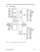
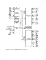
Page 117: ...2 60 Service Guide Figure 2 12 Functional block diagram CardBus Card Interface ...
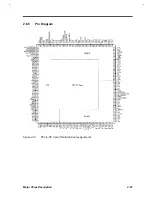
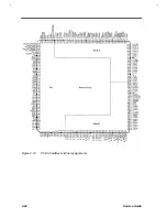
Page 119: ...2 62 Service Guide Figure 2 14 PCI to CardBus terminal assignments ...
Page 135: ...2 78 Service Guide 2 7 3 Pin Diagram Figure 2 16 NS87336VJG Pin Diagram ...
Page 145: ...2 88 Service Guide 2 8 2 Pin Diagram Figure 2 17 YMF715 Block Diagram ...
Page 185: ...Disassembly and Unit Replacement 4 5 Figure 4 3 Disassembly Sequence Flowchart ...
Page 209: ...B 2 Service Guide ...
Page 210: ...Exploded View Diagram B 3 ...

