2-98
Service Guide
2.10
T62.061.C DC-DC Converter
This compact, high efficiency DC/DC Converter fe5V, +3.3V, 2.35V/2.45V/2.9V/3.1V,
+12V and +6V five outputs up to 22 watts. And it accepts input from 7V to 21V, suitable for 3 cells
Lithium Ion or 10 cells NiMH battery input Pentium based Notebook PC.
The converter also supplies P.G. signal, 2.35V/2.45V/2.9V/3.1V switch for CPU and ON/OFF
control.
2.10.1
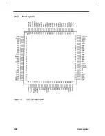
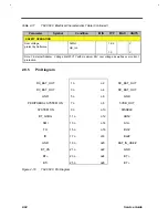
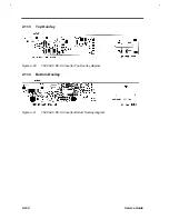
Pin Diagram
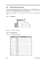
Figure 2-19
T62.061.C Pin Diagram
2.10.2
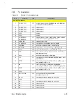
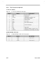
Pin Assignment
Table 2-19
T62.061.C Pin Descriptions
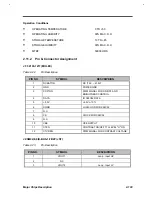
Pin No.
Description
1,2
GND
3
DC-IN
4
P.G.Vcc
5
+5.0V
6
GND
7
+6V
8
+12V
9
GND
10
+3.3V
11
5VSB
12
ON/OFF
13
P.G.
14,15
Vcpu
16,17
GND
Summary of Contents for AcerNote Light 370P
Page 6: ...vi ...
Page 26: ...1 8 Service Guide Figure 1 5 Main Board Layout Bottom Side ...
Page 49: ...System Introduction 1 31 1 5 1 3 Power Management Figure 1 14 Power Management Block Diagram ...
Page 55: ...System Introduction 1 37 1 6 System Block Diagram Figure 1 15 System Block Diagram ...
Page 64: ...Major Chips Description 2 7 2 2 5 Pin Diagram Figure 2 4 M1521 Pin Diagram ...
Page 99: ...2 42 Service Guide 2 5 3 Pin Diagram Figure 2 10 C T 65550 Pin Diagram ...
Page 117: ...2 60 Service Guide Figure 2 12 Functional block diagram CardBus Card Interface ...
Page 119: ...2 62 Service Guide Figure 2 14 PCI to CardBus terminal assignments ...
Page 135: ...2 78 Service Guide 2 7 3 Pin Diagram Figure 2 16 NS87336VJG Pin Diagram ...
Page 145: ...2 88 Service Guide 2 8 2 Pin Diagram Figure 2 17 YMF715 Block Diagram ...
Page 185: ...Disassembly and Unit Replacement 4 5 Figure 4 3 Disassembly Sequence Flowchart ...
Page 209: ...B 2 Service Guide ...
Page 210: ...Exploded View Diagram B 3 ...

