xvii
CD-ROM Specifications................................................................................................. 1-25
Battery Specifications..................................................................................................... 1-25
Charger Specifications ................................................................................................... 1-26
DC-DC Converter Specifications.................................................................................... 1-27
DC-AC Inverter Specifications ....................................................................................... 1-27
LCD Specifications ........................................................................................................ 1-28
AC Adapter Specifications ............................................................................................. 1-29
Hotkey Descriptions ....................................................................................................... 1-30
Standby Mode Conditions and Descriptions.................................................................... 1-32
Suspend Mode Conditions and Descriptions ................................................................... 1-34
Display Standby Mode Conditions and Descriptions....................................................... 1-34
Hard Disk Standby Mode Conditions and Descriptions................................................... 1-35
Location of Drivers in the System Utility CD.................................................................. 1-36
Location of Applications in the System Utility CD ......................................................... 1-36
Environmental Requirements ......................................................................................... 1-38
Mechanical Specifications .............................................................................................. 1-39
Major Chips List .............................................................................................................. 2-1
M1521 Signal Descriptions .............................................................................................. 2-8
M1523 Signal Descriptions ............................................................................................ 2-18
M7101 Pin Descriptions ................................................................................................. 2-26
M7101 Different Pin Definition Setting.......................................................................... 2-34
M7101 Original Pin Definition Setting........................................................................... 2-35
M7101 Numerical Pin List ............................................................................................. 2-36
M7101 Alphabetical Pin List.......................................................................................... 2-37
M7101 PCI Interface Lock Register................................................................................ 2-39
C&T 65550 Pin Descriptions.......................................................................................... 2-43
Flat Panel Display Interface Configurations.................................................................... 2-54
Bus Output Signal Status During Standby Mode............................................................. 2-55
PCI1131 Pin Descriptions .............................................................................................. 2-63
Summary of Contents for AcerNote Light 370P
Page 6: ...vi ...
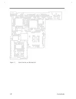
Page 26: ...1 8 Service Guide Figure 1 5 Main Board Layout Bottom Side ...
Page 49: ...System Introduction 1 31 1 5 1 3 Power Management Figure 1 14 Power Management Block Diagram ...
Page 55: ...System Introduction 1 37 1 6 System Block Diagram Figure 1 15 System Block Diagram ...
Page 64: ...Major Chips Description 2 7 2 2 5 Pin Diagram Figure 2 4 M1521 Pin Diagram ...
Page 99: ...2 42 Service Guide 2 5 3 Pin Diagram Figure 2 10 C T 65550 Pin Diagram ...
Page 117: ...2 60 Service Guide Figure 2 12 Functional block diagram CardBus Card Interface ...
Page 119: ...2 62 Service Guide Figure 2 14 PCI to CardBus terminal assignments ...
Page 135: ...2 78 Service Guide 2 7 3 Pin Diagram Figure 2 16 NS87336VJG Pin Diagram ...
Page 145: ...2 88 Service Guide 2 8 2 Pin Diagram Figure 2 17 YMF715 Block Diagram ...
Page 185: ...Disassembly and Unit Replacement 4 5 Figure 4 3 Disassembly Sequence Flowchart ...
Page 209: ...B 2 Service Guide ...
Page 210: ...Exploded View Diagram B 3 ...


