BIOS Setup Information
3-7
3.4.3
System Boot Drive Control
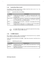
This parameter determines which drive the notebook boots from when you turn it on. The
following table lists the three possible settings.
Table 3-4
System Boot Drive Control Settings
Setting
Description
Drive A Then C
(default)
Notebook boots from floppy drive A. If there is no system disk in drive A, the
notebook boots from hard disk C. If the hard disk is a non-system disk, an error
message appears.
Drive C Then A
Notebook boots from hard disk C. If hard disk C is not a system disk, the notebook
boots from floppy drive A. If no diskette is present or if the diskette in floppy drive
A is a non-system disk, an error message appears.
Drive C
Notebook boots from hard disk C. If hard disk C is not a system disk, an error
message appears.
Drive A
Notebook boots from floppy drive A. If no diskette is present or if the diskette in
floppy drive A is a non-system disk, an error message appears.
An installed PCMCIA bootable card overrides the System Boot Drive setting.
The notebook supports SRAM card boot.
3.4.4
CD-ROM Bootable
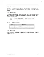
When enabled the notebook checks the CD-ROM drive first and boots from there, if possible,
before checking the System Boot Drive control setting.
There are two image types/formats for CD-ROMs - floppy drive and hard disk. See Table 3-5 for a
description.
Table 3-5
CD-ROM Image Descriptions
Image Type
Upon Boot-up…
Floppy Drive
CD-ROM drive becomes drive A and the floppy drive becomes drive B. The hard
disk drive remains drive C.
Hard Disk
CD-ROM drive becomes drive C and the hard disk drive becomes drive D. The
floppy drive remains drive A.
Summary of Contents for AcerNote Light 370P
Page 6: ...vi ...
Page 26: ...1 8 Service Guide Figure 1 5 Main Board Layout Bottom Side ...
Page 49: ...System Introduction 1 31 1 5 1 3 Power Management Figure 1 14 Power Management Block Diagram ...
Page 55: ...System Introduction 1 37 1 6 System Block Diagram Figure 1 15 System Block Diagram ...
Page 64: ...Major Chips Description 2 7 2 2 5 Pin Diagram Figure 2 4 M1521 Pin Diagram ...
Page 99: ...2 42 Service Guide 2 5 3 Pin Diagram Figure 2 10 C T 65550 Pin Diagram ...
Page 117: ...2 60 Service Guide Figure 2 12 Functional block diagram CardBus Card Interface ...
Page 119: ...2 62 Service Guide Figure 2 14 PCI to CardBus terminal assignments ...
Page 135: ...2 78 Service Guide 2 7 3 Pin Diagram Figure 2 16 NS87336VJG Pin Diagram ...
Page 145: ...2 88 Service Guide 2 8 2 Pin Diagram Figure 2 17 YMF715 Block Diagram ...
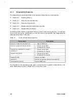
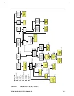
Page 185: ...Disassembly and Unit Replacement 4 5 Figure 4 3 Disassembly Sequence Flowchart ...
Page 209: ...B 2 Service Guide ...
Page 210: ...Exploded View Diagram B 3 ...

