3-8
Service Guide
3.4.5
Serial Port 1 Base Address
The serial port can accommodate a modem, serial mouse, serial printer, or other serial devices.
The default setting for the serial port base address is
3F8h(IRQ 4)
1
.
Other options include:
•
2F8h(IRQ 3)
•
3E8h(IRQ 4)
•
2E8h(IRQ 3)
•
Disabled
Make sure the serial port base address does not conflict with the address used by a PCMCIA card,
if one is installed.
3.4.6
Parallel Port Base Address
The parallel port can accommodate a parallel printer or other parallel devices. The default setting
for the parallel port base address is
[378h(IRQ 7)]
1
. The other options for this parameter are:
•
278h(IRQ 5)
•
3BCh(IRQ 7)
•
Disabled
3.4.7
Parallel Port Operation Mode
The parallel port supports four operation modes:
•
Standard and Bidirectional
•
Extended Capabilities Port(ECP)
•
Standard and Unidirectional
•
Enhanced Parallel Port(EPP)
ECP or Extended Capabilities Port supports a 16-byte FIFO (first in, first out) which can be
accessed by host DMA cycles and PIO cycles. ECP boosts I/O bandwidth to meet the demands
of high-performance peripherals. EPP or Enhanced Parallel Port is a parallel port interface that
greatly improves performance for bi-directional block-mode data transfers. EPP provides greater
throughput by supporting faster transfer times and a mechanism that allows the host to address
peripheral device registers directly.
1 The parameter value is the base address expressed in hexadecimal.
Summary of Contents for AcerNote Light 370P
Page 6: ...vi ...
Page 26: ...1 8 Service Guide Figure 1 5 Main Board Layout Bottom Side ...
Page 49: ...System Introduction 1 31 1 5 1 3 Power Management Figure 1 14 Power Management Block Diagram ...
Page 55: ...System Introduction 1 37 1 6 System Block Diagram Figure 1 15 System Block Diagram ...
Page 64: ...Major Chips Description 2 7 2 2 5 Pin Diagram Figure 2 4 M1521 Pin Diagram ...
Page 99: ...2 42 Service Guide 2 5 3 Pin Diagram Figure 2 10 C T 65550 Pin Diagram ...
Page 117: ...2 60 Service Guide Figure 2 12 Functional block diagram CardBus Card Interface ...
Page 119: ...2 62 Service Guide Figure 2 14 PCI to CardBus terminal assignments ...
Page 135: ...2 78 Service Guide 2 7 3 Pin Diagram Figure 2 16 NS87336VJG Pin Diagram ...
Page 145: ...2 88 Service Guide 2 8 2 Pin Diagram Figure 2 17 YMF715 Block Diagram ...
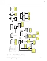
Page 185: ...Disassembly and Unit Replacement 4 5 Figure 4 3 Disassembly Sequence Flowchart ...
Page 209: ...B 2 Service Guide ...
Page 210: ...Exploded View Diagram B 3 ...

