A p
A p p e n d
p e n d i x C
i x C
Spare Parts
Spare Parts
C-
1
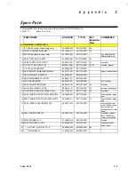
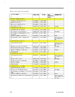
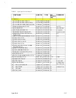
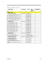
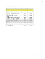
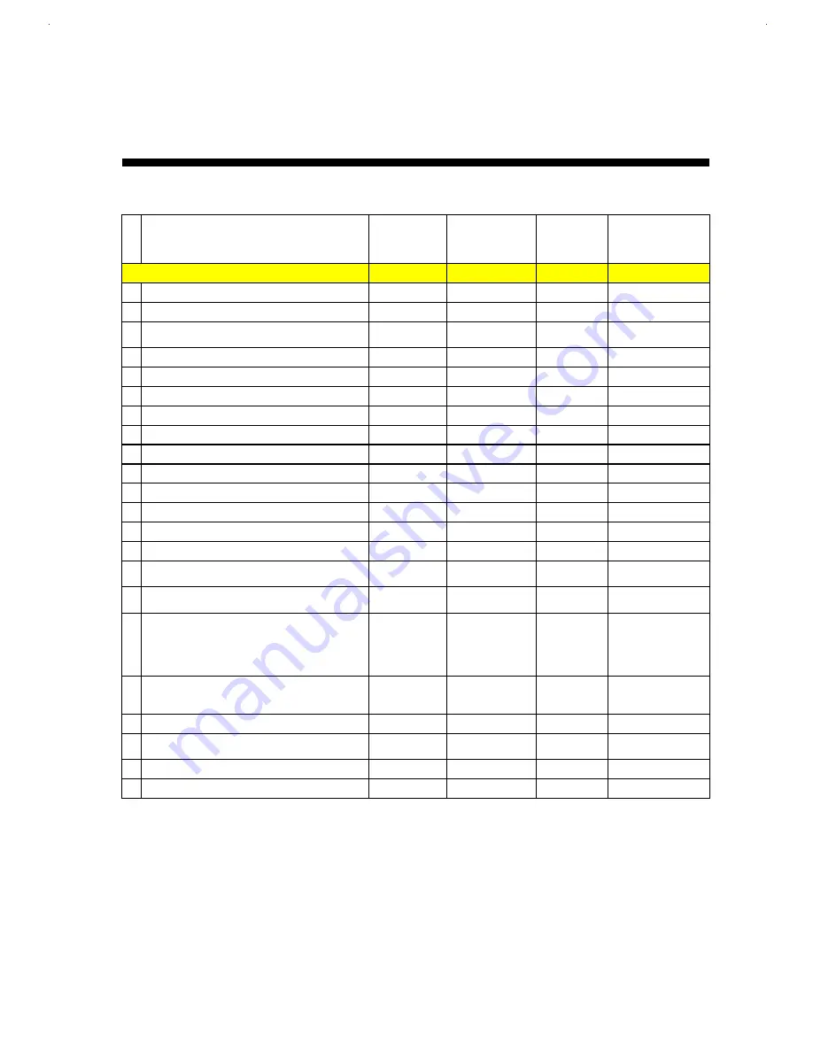
This appendix lists the spare parts of the notebook TI EXTENSA 610.
Table C-1
Spare Parts List
PART NAME
ACER P/N
TI P/N
Ref.
Exploded
View
COMMENTS
<< MECHANICAL & MODULES >>
1 IC CHARGE (power supply charger bd)
05.62062.020
9811768-0001
56
2 FAN 5V UDQFC3E09 105MM
23.10029.011
9811769-0001
32
3 ADT (AC Adapter w/o power cord)
25.10052.001
9811770-0001
see options for AC
adapter with cord
4 HEAT SINK-U(2) AL AN370
34.46925.001
981177100001
30
5 CASE UPPER (TOP) 370P/TI
39.46901.031
9811772-0001
21
w/o label
6 C.A FPC TOUCH PAD 370P
6M.48415.001
9811774-0001
24, 25
w/cable, bracket
7 C.A FPC AUDIO BD 370P
50.48402.001
9811775-0001
8 HDD 1083MB TOSHIBA/MK1002MAV
56.02775.001
9811776-0001
without case or cable
9 HDD 1440MB HIT-DK225A-14
56.02568.031
9815585-0001
10 HDD 2160MB IBM/DTNA -22160
56.02941.011
9815586-0001
11 HDD TRANSFER BD
55.48403.001
9811802-0001
w/ connector
12 ASSY HDD UPPER COVER
60.48412.101
9811783-0001
44
w/mylar
13 ASSY HDD LOWER COVER
60.48418.101
9811785-0001
46
w/mylar, belt sponge
14 TOUCHPAD SYNAP/TM1202MPU-156-1
56.17450.011
9811777-0001
22
w/o label
15 ASSY HINGE (COVER) CAP(R) 050 AN370
60.46906.001
9811778-0001
7
w/net speaker, hinge
cap
16 ASSY HINGE (COVER) CAP(L) 050 AN370
60.46906.011
9811779-0001
10
w/net speaker, hinge
cap
17 ASSY LOWER CASE (BASE) 370P
60.48411.001
9811782-0001
w/bracket, pcmcia
cover, I/o door, knob
power, foot rub,
cover ext FDD, simm
cover
18 ASSY CHASSIS AN370P
60.48413.001
9811784-0001
w/speaker, battery
bd, PCMCIA door,
mylar, cover switch
19 FDD EXTERNAL 370
91.46905.012
9811788-0001
w/cable
20 ASSY CD-ROM KIT (V32)
91.46928.023
9811789-0001
w/bracket, cable,
bezel, knob
21 C.A. ASSY CD-FPC,EXT 61X
50.46903.002
9815582-0001
58
22 CD-ROM BEZEL
41.46903.001
9815587-0001
Summary of Contents for AcerNote Light 370P
Page 6: ...vi ...
Page 26: ...1 8 Service Guide Figure 1 5 Main Board Layout Bottom Side ...
Page 49: ...System Introduction 1 31 1 5 1 3 Power Management Figure 1 14 Power Management Block Diagram ...
Page 55: ...System Introduction 1 37 1 6 System Block Diagram Figure 1 15 System Block Diagram ...
Page 64: ...Major Chips Description 2 7 2 2 5 Pin Diagram Figure 2 4 M1521 Pin Diagram ...
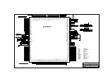
Page 99: ...2 42 Service Guide 2 5 3 Pin Diagram Figure 2 10 C T 65550 Pin Diagram ...
Page 117: ...2 60 Service Guide Figure 2 12 Functional block diagram CardBus Card Interface ...
Page 119: ...2 62 Service Guide Figure 2 14 PCI to CardBus terminal assignments ...
Page 135: ...2 78 Service Guide 2 7 3 Pin Diagram Figure 2 16 NS87336VJG Pin Diagram ...
Page 145: ...2 88 Service Guide 2 8 2 Pin Diagram Figure 2 17 YMF715 Block Diagram ...
Page 185: ...Disassembly and Unit Replacement 4 5 Figure 4 3 Disassembly Sequence Flowchart ...
Page 209: ...B 2 Service Guide ...
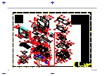
Page 210: ...Exploded View Diagram B 3 ...

