C-
2
Service Guide
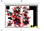
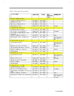
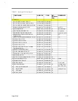
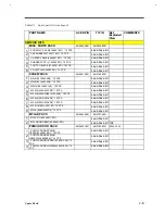
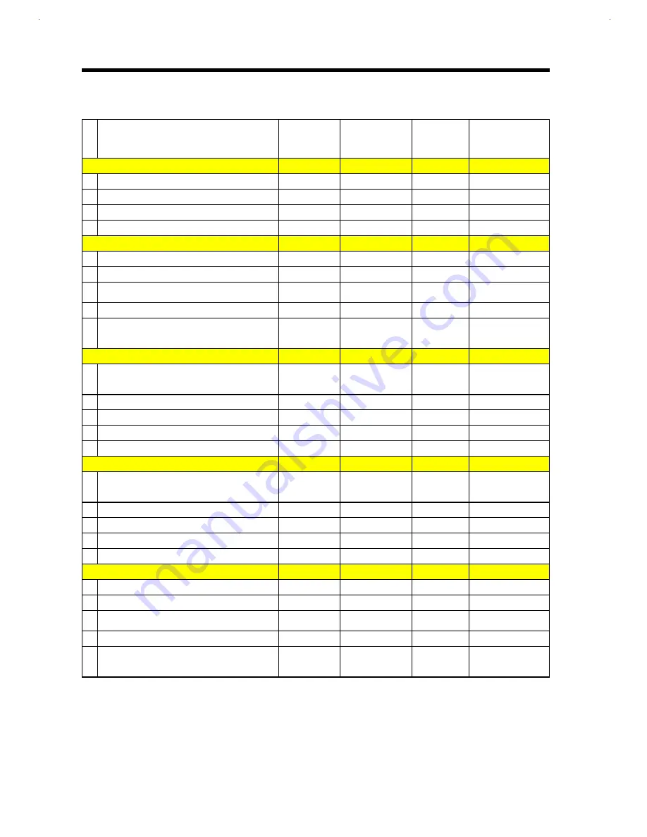
Table C1 Spare parts list (continued)
PART NAME
ACER P/N
TI P/N
Ref.
Exploded
View
COMMENTS
<< DISPLAY COMMON PARTS >>
1 HINGE (L), SAE AN370, EXT 61X
34.46909.001
9813520-0001
2 HINGE ( R), EXT. 61X
34.46905.001
9811814-0001
3 MYLAR, LCD, 100MM, EXT 61X
40.46928.001
9811817-0001
4 LCD LATCH, EXT 61X
6M.48410.001
9815579-0001
3, 4
w/ spring
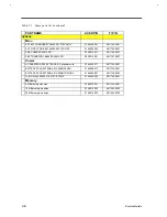
<< LCD KIT (STN) >> Hitachi 11.3"
1 INVERTER T62.064.C.00 370P
19.21030.101
9811790-0001
12
3 C.A 31P FPC 11.3"STN 370(W.C)
6M.48412.001
9811791-0001
1,2
w/ tail diaper
4 (LCD PANEL) LCDM LMG9900 11.3 STN
SVGA HIT
56.07355.011
9811792-0001
1
5 ASSY LCD BEZEL(11.3")050 370P
60.46902.101
9811793-0001
14
w/lens
6 COVER ASSY LCD(11.3 HI) 050 370PT
60.48401.151
9811794-0001
w/lens, diaper, assy
latch, hinge(R); no TI
logo
<< LCD KIT (STN) >> Sanyo 11.3"
1 COVER ASSY LCD PNL
60.48401.151
9811794-0001
1
w/lens, diaper assy.,
latch, hinge(R), no TI
logo
2 ASSY C.A 31P FPC 11.3" STN 370
6M.48412.001
9811791-0001
1,2
w/ tail diaper
3 (LCD PANEL )LCDM (sanyo 11.3" DSTN)
56.07469.001
9815588-0001
4 ASSY LCD BEZEL(11.3") 050 370P
60.46902.101
9811793-0001
14
W/LENS
5 INVERTER BD
19.21030.101
9811790-0001
12
<< LCD KIT (TFT) >> LG 12.1"
1 COVER ASSY LCD PNL
60.48401.171
9815589-0001
1
w/lens, diaper assy.,
latch, hinge(R), no TI
logo
2 ASSY C.A FPC, LG 12.1
6M.48414.001
9815591-0001
1,2
w/ tail diaper
3 LCDM LP 121S 12.1"(LCD PANEL)
56.07530.011
9815590-0001
4 ASSY LCD BEZEL
60.48402.001
9815592-0001
14
W/LENS
5 INVERTER BD
19.21030.081
9815593-0001
12
<< LCD KIT (TFT) >> 11.3" IBM
1 INVERTER T62.064.C.00 370P
19.21030.101
9811790-0001
12
2 C.A FPC 11.3TFT/SHARP 370(W.C)
50.46917.021
9811795-0001
1,2
w/ tail diaper
3 (LCD PANEL) LCM ITSV45E 11.3"TFT SVGA
IBM
56.07469.101
9811796-0001
4 ASSY LCD BEZEL(11.3")050 370P
60.46902.101
9811793-0001
14
w/ lens
5 COVER ASSY LCD PNL(11.3TFT)IBM 370PTI
60.48401.161
9811797-0001
1
w/lens, diaper, latch
assy., hinge(R); and
no TI logo
Summary of Contents for AcerNote Light 370P
Page 6: ...vi ...
Page 26: ...1 8 Service Guide Figure 1 5 Main Board Layout Bottom Side ...
Page 49: ...System Introduction 1 31 1 5 1 3 Power Management Figure 1 14 Power Management Block Diagram ...
Page 55: ...System Introduction 1 37 1 6 System Block Diagram Figure 1 15 System Block Diagram ...
Page 64: ...Major Chips Description 2 7 2 2 5 Pin Diagram Figure 2 4 M1521 Pin Diagram ...
Page 99: ...2 42 Service Guide 2 5 3 Pin Diagram Figure 2 10 C T 65550 Pin Diagram ...
Page 117: ...2 60 Service Guide Figure 2 12 Functional block diagram CardBus Card Interface ...
Page 119: ...2 62 Service Guide Figure 2 14 PCI to CardBus terminal assignments ...
Page 135: ...2 78 Service Guide 2 7 3 Pin Diagram Figure 2 16 NS87336VJG Pin Diagram ...
Page 145: ...2 88 Service Guide 2 8 2 Pin Diagram Figure 2 17 YMF715 Block Diagram ...
Page 185: ...Disassembly and Unit Replacement 4 5 Figure 4 3 Disassembly Sequence Flowchart ...
Page 209: ...B 2 Service Guide ...
Page 210: ...Exploded View Diagram B 3 ...

