C-
4
Service Guide
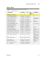
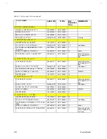
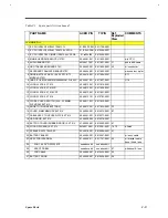
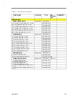
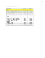
Table C1 Spare parts list (continued)
PART NAME
ACER P/N
TI P/N
Ref.
Exploded
View
COMMENTS
KEYBOARDS
KB-84 KEY KAS1901-0161R US 370 (US)
90.46907.001
9805728-0001
27
w/cable
Keyboard(UK)
90.46907.00U
9805758-0002
27
w/cable
Keyboard(Germany)
90.46907.00G
9805758-0003
27
w/cable
Keyboard(French)
90.46907.00F
9805758-0004
27
w/cable
Keyboard(Spanish)
90.46907.00S
9805758-0005
27
w/cable
Keyboard(Sws/Ger)
90.46907.007
9805758-0006
27
w/cable
Keyboard(Italian)
90.46907.00I
9805758-0007
27
w/cable
Keyboard(Portuguese)
90.46907.00P
9805758-0008
27
w/cable
Keyboard(Sweden)
90.46907.00W
9805758-0010
27
w/cable
Keyboard(Denmark)
90.46907.00D
9805758-0012
27
w/cable
Keyboard(Norwegian)
90.46907.00N
9805758-0013
27
w/cable
Keyboard(Finland)
90.46907.008
9805758-0014
27
w/cable
Keyboard(Belgium)
90.46907.00B
9805758-0015
27
w/cable
Keyboard(Chinese)
90.46907.00C
9805758-0019
27
w/cable
Keyboard(Korean)
90.46907.00K
9805758-0020
27
w/cable
Keyboard(Japanese)
90.46907.00J
9805758-0021
27
w/cable
Summary of Contents for AcerNote Light 370P
Page 6: ...vi ...
Page 26: ...1 8 Service Guide Figure 1 5 Main Board Layout Bottom Side ...
Page 49: ...System Introduction 1 31 1 5 1 3 Power Management Figure 1 14 Power Management Block Diagram ...
Page 55: ...System Introduction 1 37 1 6 System Block Diagram Figure 1 15 System Block Diagram ...
Page 64: ...Major Chips Description 2 7 2 2 5 Pin Diagram Figure 2 4 M1521 Pin Diagram ...
Page 99: ...2 42 Service Guide 2 5 3 Pin Diagram Figure 2 10 C T 65550 Pin Diagram ...
Page 117: ...2 60 Service Guide Figure 2 12 Functional block diagram CardBus Card Interface ...
Page 119: ...2 62 Service Guide Figure 2 14 PCI to CardBus terminal assignments ...
Page 135: ...2 78 Service Guide 2 7 3 Pin Diagram Figure 2 16 NS87336VJG Pin Diagram ...
Page 145: ...2 88 Service Guide 2 8 2 Pin Diagram Figure 2 17 YMF715 Block Diagram ...
Page 185: ...Disassembly and Unit Replacement 4 5 Figure 4 3 Disassembly Sequence Flowchart ...
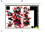
Page 209: ...B 2 Service Guide ...
Page 210: ...Exploded View Diagram B 3 ...

