iv
Appendix E
BIOS POST Checkpoints
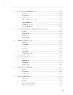
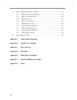
This appendix lists all the BIOS POST checkpoints.
Appendix F
Technical Bulletins and Updates
This appendix reserves a space for technical bulletins and future updates.
Appendix G
Forms
This appendix contains standard forms that can help improve customer service.
Related product information
AcerNote 370P User's Manual contains system description and general operating instructions.
M1521, M1523 and M7101 Data Sheets contain information on the Acer chips.
C&T 65550 Data Sheet contains detailed information on the Chips & Tech. VGA controller.
TI PCI1131 Data Sheet contains detailed information on the Texas Instrument PCMCIA controller.
NS87336VJG Data Sheet contains detailed information on the NS super I/O controller.
YMF715 Data Sheet contains detailed information on the Yamaha YMF715 audio controller.
T62.062.C, T62.061.C, T62.064.C, and T62.066.C Data Sheets contain detailed information on the Ambit
components.
Summary of Contents for AcerNote Light 370P
Page 6: ...vi ...
Page 26: ...1 8 Service Guide Figure 1 5 Main Board Layout Bottom Side ...
Page 49: ...System Introduction 1 31 1 5 1 3 Power Management Figure 1 14 Power Management Block Diagram ...
Page 55: ...System Introduction 1 37 1 6 System Block Diagram Figure 1 15 System Block Diagram ...
Page 64: ...Major Chips Description 2 7 2 2 5 Pin Diagram Figure 2 4 M1521 Pin Diagram ...
Page 99: ...2 42 Service Guide 2 5 3 Pin Diagram Figure 2 10 C T 65550 Pin Diagram ...
Page 117: ...2 60 Service Guide Figure 2 12 Functional block diagram CardBus Card Interface ...
Page 119: ...2 62 Service Guide Figure 2 14 PCI to CardBus terminal assignments ...
Page 135: ...2 78 Service Guide 2 7 3 Pin Diagram Figure 2 16 NS87336VJG Pin Diagram ...
Page 145: ...2 88 Service Guide 2 8 2 Pin Diagram Figure 2 17 YMF715 Block Diagram ...
Page 185: ...Disassembly and Unit Replacement 4 5 Figure 4 3 Disassembly Sequence Flowchart ...
Page 209: ...B 2 Service Guide ...
Page 210: ...Exploded View Diagram B 3 ...


