System Introduction
1-
23
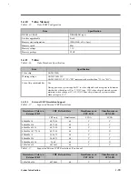
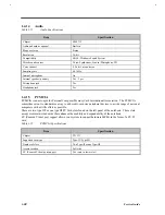
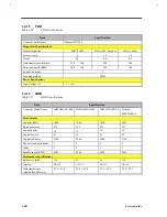
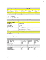
1.4.16
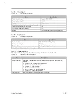
Touchpad
Table 1-23
Touchpad Specifications
Item
Specification
Vendor & model name
Synaptics TM1002MPU
Power supply voltage (V)
5
±
10%
Location
Palm-rest center
Internal & external pointing device work simultaneously
Yes
Support external pointing device hot plug
Yes
X/Y position resolution (points/mm)
20
Interface
PS/2 (compatible with Microsoft mouse driver)
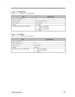
1.4.17
Keyboard
Table 1-24
Keyboard Specifications
Item
Specification
Vendor & model name
SMK KAS1901-0161R (English)
Total number of keypads
84/85 keys
Windows 95 keys
Yes, (Logo key / Application key):
Internal & external keyboard work simultaneously
Yes
1.4.17.1
Windows 95 Keys
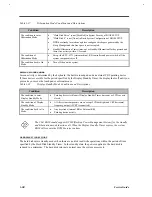
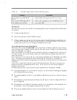
The keyboard has two keys that perform Windows 95-specific functions. See Table 1-26.
Table 1-25
Windows 95 Key Descriptions
Key
Description
Windows logo key
Start button. Combinations with this key performs special functions. Below are a few
examples:
•
W Tab Activate next Taskbar button
•
W E Explore My Computer
•
W F Find Document
•
W M Minimize All
•
Shift + W M Undo Minimize All
•
W R Display Run dialog box
Application key
Opens the application’s context menu (same as right-click).
Summary of Contents for AcerNote Light 370P
Page 6: ...vi ...
Page 26: ...1 8 Service Guide Figure 1 5 Main Board Layout Bottom Side ...
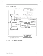
Page 49: ...System Introduction 1 31 1 5 1 3 Power Management Figure 1 14 Power Management Block Diagram ...
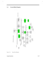
Page 55: ...System Introduction 1 37 1 6 System Block Diagram Figure 1 15 System Block Diagram ...
Page 64: ...Major Chips Description 2 7 2 2 5 Pin Diagram Figure 2 4 M1521 Pin Diagram ...
Page 99: ...2 42 Service Guide 2 5 3 Pin Diagram Figure 2 10 C T 65550 Pin Diagram ...
Page 117: ...2 60 Service Guide Figure 2 12 Functional block diagram CardBus Card Interface ...
Page 119: ...2 62 Service Guide Figure 2 14 PCI to CardBus terminal assignments ...
Page 135: ...2 78 Service Guide 2 7 3 Pin Diagram Figure 2 16 NS87336VJG Pin Diagram ...
Page 145: ...2 88 Service Guide 2 8 2 Pin Diagram Figure 2 17 YMF715 Block Diagram ...
Page 185: ...Disassembly and Unit Replacement 4 5 Figure 4 3 Disassembly Sequence Flowchart ...
Page 209: ...B 2 Service Guide ...
Page 210: ...Exploded View Diagram B 3 ...

