Major Chips Description
2-27
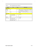
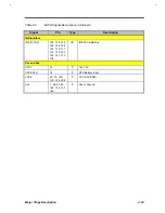
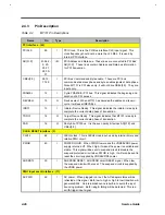
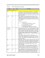
Table 2-4
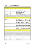
M7101 Pin Descriptions (Continued)
Name
No.
Type
Description
PMU Input event interface : (11)
LBJ
47
I
Low Battery. First stage battery low indication. If low is detected
and Low Battery Timer is timeout, then battery low 1 SMIJ will be
generated every programmed interval time until battery low 2 SMIJ
is asserted or LB timer is reset. No debounce circuit is built in. Only
low level is detected.
LLBJ
48
I
Low Low Battery. Second stage battery low indication. If low is
detected and Low Low Battery Timer is timeout, then battery low 2
SMIJ will be generated every programmed interval time until both
LB and LLB timer are reset. No debounce circuit is built in. Only low
level is detected.
LLBJ LBJ
H H Normal condition
H L Low Battery SMIJ will generate every interval.
Low Low Battery SMIJ will not happen.
L X Low Battery SMIJ will not happen.
Low Low Battery SMIJ will generate every interval.
COVSW
/SUSTAT2
41
I/O
Cover switch (when 0F8h, D7=1). Cover switch status input. When
COVER is closed, the cover switch is also pressed and a COVSW
SMIJ will be generated. When COVER is opened, the cover switch
will be released, a COVSW SMIJ will be generated, too. Moreover,
both close and open will generate a doze-to-on or sleep-to-on SMIJ
to wake the system up if the system is in Doze or Sleep state,
respectively. Debounce circuit is built in. It detects both rising and
falling edge.
Suspend status 2 (when 0F8h, D7=0, it is default value). It is
suspend status 2 signal during 0/5V suspend system. It will be low
in normal. When writing to port 0FAh, it will go high to close the
charger. Any event of RI, RTC or HOTKEYJ will wake it up, and let
this pin go low again.
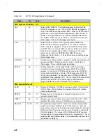
RI
42
I
Modem Ring. Modem ring input. A programmable ring counter will
count the ring pulse. If the ring pulse reaches the counter‘s setting
value, a doze-to-on SMIJ or sleep-to-on SMIJ will be generated to
wakeup the system. If the system is already at on state, there will be
no new event or action. No debounce circuit is built in. It only
detects rising edge.
RTC
43
I
RTC Alarm wakeup. A low to high transition of this signal will
generate a doze-to-on or sleep-to-on SMIJ to wakeup the system. If
the system is already at on state, there will be no new event or
action. No debounce circuit is built in. It only detects rising edge.
DRQ
52
I
Floppy DMA Request. A low to high transition of this signal will
generate a doze-to-on or sleep-to-on SMIJ to wakeup the system. If
the system is at on state already, there will be no new event or
action. No debounce circuit is built in. It only detects rising edge.
Summary of Contents for AcerNote Light 370P
Page 6: ...vi ...
Page 26: ...1 8 Service Guide Figure 1 5 Main Board Layout Bottom Side ...
Page 49: ...System Introduction 1 31 1 5 1 3 Power Management Figure 1 14 Power Management Block Diagram ...
Page 55: ...System Introduction 1 37 1 6 System Block Diagram Figure 1 15 System Block Diagram ...
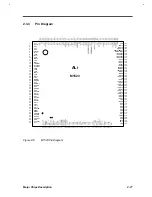
Page 64: ...Major Chips Description 2 7 2 2 5 Pin Diagram Figure 2 4 M1521 Pin Diagram ...
Page 99: ...2 42 Service Guide 2 5 3 Pin Diagram Figure 2 10 C T 65550 Pin Diagram ...
Page 117: ...2 60 Service Guide Figure 2 12 Functional block diagram CardBus Card Interface ...
Page 119: ...2 62 Service Guide Figure 2 14 PCI to CardBus terminal assignments ...
Page 135: ...2 78 Service Guide 2 7 3 Pin Diagram Figure 2 16 NS87336VJG Pin Diagram ...
Page 145: ...2 88 Service Guide 2 8 2 Pin Diagram Figure 2 17 YMF715 Block Diagram ...
Page 185: ...Disassembly and Unit Replacement 4 5 Figure 4 3 Disassembly Sequence Flowchart ...
Page 209: ...B 2 Service Guide ...
Page 210: ...Exploded View Diagram B 3 ...

