Major Chips Description
2-97
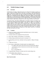
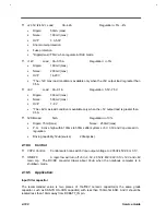
When system on if Adapter not inserted and battery voltage lower than BL3 voltage , then system
will be turned off by the charger module.
In addition, when system sends a ‘disable’ signal to charger module, system will be turned off by
the charger module immedietly.
2.9.7.3
Safety Concerns
For safety, the charger module inhibits charging until the battery voltage and temperature are
within the configured ranges. If the voltage is less than the low voltage threshold , the charger
module provides trickle current to charge the battery . This prevents fast charging could possibly
damage the battery. Also when the temperature of battery pack is over the temperature threshold,
the charger module will not charge the battery until its temperature within a configured range. This
prevents reducing the battery’s service life.
Concludely, in order to ensure safety for the battery and system, charge may be terminated when
the battery temperature over a threshold or after a safety time period.
Summary of Contents for AcerNote Light 370P
Page 6: ...vi ...
Page 26: ...1 8 Service Guide Figure 1 5 Main Board Layout Bottom Side ...
Page 49: ...System Introduction 1 31 1 5 1 3 Power Management Figure 1 14 Power Management Block Diagram ...
Page 55: ...System Introduction 1 37 1 6 System Block Diagram Figure 1 15 System Block Diagram ...
Page 64: ...Major Chips Description 2 7 2 2 5 Pin Diagram Figure 2 4 M1521 Pin Diagram ...
Page 99: ...2 42 Service Guide 2 5 3 Pin Diagram Figure 2 10 C T 65550 Pin Diagram ...
Page 117: ...2 60 Service Guide Figure 2 12 Functional block diagram CardBus Card Interface ...
Page 119: ...2 62 Service Guide Figure 2 14 PCI to CardBus terminal assignments ...
Page 135: ...2 78 Service Guide 2 7 3 Pin Diagram Figure 2 16 NS87336VJG Pin Diagram ...
Page 145: ...2 88 Service Guide 2 8 2 Pin Diagram Figure 2 17 YMF715 Block Diagram ...
Page 185: ...Disassembly and Unit Replacement 4 5 Figure 4 3 Disassembly Sequence Flowchart ...
Page 209: ...B 2 Service Guide ...
Page 210: ...Exploded View Diagram B 3 ...

