Major Chips Description
2-105
2.12
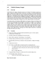
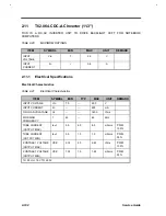
T62.066.C DC-AC Inverter (12.1")
This is a DC-AC inverter unit to drive Backlight CCFT for
notebook computers
Table 2-23
MAXIMUM RATINGS
ITEM
SYMBOL
MIN
MAX
UNIT
REMARK
INPUT
VOLTAGE
Vin
7
21
V
INPUT
CURRENT
Iin
--
0.65
A
2.12.1
Electrical Specifications
Electrical Characteristics
Table 2-24
Electrical Characteristics
ITEM
SYMBOL
MIN
TYP
MAX
UNIT
REMARK
INPUT VOLTAGE
Vin
7.0
--
21.0
V
INPUT CURRENT
Iin
--
--
650
mA
NO LOAD VOLATAGE
Vs
--
--
1400
Vrms
WORKING
FREQUENCY
f
45
--
60
KHz
TUBE CURRENT
(OUTPUT MAX.)
Iout
5.5
6.0
6.5
mArms
PWM
100%
TUBE CURRENT
(OUTPUT MIN.)
Iout
0.5
1.0
1.5
mArms
PWM
25%
Tc=25 Vin=7.0V TO 21.0V
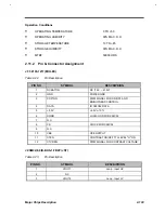
Operation Conditions
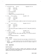
•
OPERATING TEMPERATURE
0 TO +50
•
OPERATING HUMIDITY
90% MAX. R.H
•
STORAGE TEMPERATURE
10 TO +85
•
STORAGE HUMIDITY
90% MAX. R.H
•
MTBF
50000 HRS
Summary of Contents for AcerNote Light 370P
Page 6: ...vi ...
Page 26: ...1 8 Service Guide Figure 1 5 Main Board Layout Bottom Side ...
Page 49: ...System Introduction 1 31 1 5 1 3 Power Management Figure 1 14 Power Management Block Diagram ...
Page 55: ...System Introduction 1 37 1 6 System Block Diagram Figure 1 15 System Block Diagram ...
Page 64: ...Major Chips Description 2 7 2 2 5 Pin Diagram Figure 2 4 M1521 Pin Diagram ...
Page 99: ...2 42 Service Guide 2 5 3 Pin Diagram Figure 2 10 C T 65550 Pin Diagram ...
Page 117: ...2 60 Service Guide Figure 2 12 Functional block diagram CardBus Card Interface ...
Page 119: ...2 62 Service Guide Figure 2 14 PCI to CardBus terminal assignments ...
Page 135: ...2 78 Service Guide 2 7 3 Pin Diagram Figure 2 16 NS87336VJG Pin Diagram ...
Page 145: ...2 88 Service Guide 2 8 2 Pin Diagram Figure 2 17 YMF715 Block Diagram ...
Page 185: ...Disassembly and Unit Replacement 4 5 Figure 4 3 Disassembly Sequence Flowchart ...
Page 209: ...B 2 Service Guide ...
Page 210: ...Exploded View Diagram B 3 ...

