3-2
Service Guide
3.2
Entering Setup
Press
F2
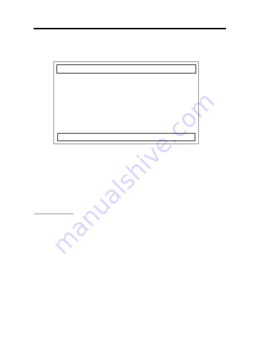
during POST to enter Setup. The BIOS Utility main screen displays.
Setup Utility
Basic System Settings
System Security
Power Management Settings
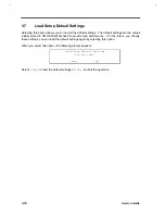
Load Setup Default Settings
↑↓
=Move Highlight Bar,
↵
=Select, Esc=Exit
There are four main menu items:
•
Basic System Settings
•
System Security
•
Power Management Settings
•
Load Setup Default Settings
Read through the Setup Screen Notes before navigating the Setup screens.
SETUP SCREEN NOTES
•
From the main menu, press
↑↑
,
↓↓
,
←
←
or
→
→
to move from one menu item to another and press
Enter to enter the selected menu.
•
When accessing multi-page sections, press PgDn and PgUp to go through the pages.
•
Parameters displayed in low brightness (grayed-out) are not user-configurable. The notebook
detects and sets the values for these parameters.
•
Press
↑↑
or
↓↓
to move from one parameter to another. Press
←
←
or
→
→
to change parameter
settings. You have to change some settings when you add a component to the notebook.
•
Most of the Setup parameters are self-explanatory. Press F1 for help on individual
parameters.
Summary of Contents for AcerNote Light 370P
Page 6: ...vi ...
Page 26: ...1 8 Service Guide Figure 1 5 Main Board Layout Bottom Side ...
Page 49: ...System Introduction 1 31 1 5 1 3 Power Management Figure 1 14 Power Management Block Diagram ...
Page 55: ...System Introduction 1 37 1 6 System Block Diagram Figure 1 15 System Block Diagram ...
Page 64: ...Major Chips Description 2 7 2 2 5 Pin Diagram Figure 2 4 M1521 Pin Diagram ...
Page 99: ...2 42 Service Guide 2 5 3 Pin Diagram Figure 2 10 C T 65550 Pin Diagram ...
Page 117: ...2 60 Service Guide Figure 2 12 Functional block diagram CardBus Card Interface ...
Page 119: ...2 62 Service Guide Figure 2 14 PCI to CardBus terminal assignments ...
Page 135: ...2 78 Service Guide 2 7 3 Pin Diagram Figure 2 16 NS87336VJG Pin Diagram ...
Page 145: ...2 88 Service Guide 2 8 2 Pin Diagram Figure 2 17 YMF715 Block Diagram ...
Page 185: ...Disassembly and Unit Replacement 4 5 Figure 4 3 Disassembly Sequence Flowchart ...
Page 209: ...B 2 Service Guide ...
Page 210: ...Exploded View Diagram B 3 ...

