Disassembly and Unit Replacement
4-3
4.1.2
Connector Types
There are two kinds of connectors on the main board:
•
Connectors with no locks
Unplug the cable by simply pulling out the cable from the connector.
•
Connectors with locks
You can use a plastic stick to lock and unlock connectors with locks.
The cables used here are special FPC (flexible printed-circuit)
cables, which are more delicate than normal plastic-enclosed
cables. Therefore, to prevent damage, make sure that you unlock
the connectors before pulling out the cables. Do not force cables
out of the connectors.
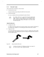
CONNECTORS WITH LOCKS
•
Unplugging the Cable
To unplug the cable, first unlock the connector by pulling up the two clasps on both sides of
the connector with a plastic stick. Then carefully pull out the cable from the connector.
•
Plugging the Cable
To plug the cable back, first make sure that the connector is unlocked, then plug the cable
into the connector. With a plastic stick, press the two clasps on both sides of the connector to
secure the cables in place.
Figure 4-2
Using Connectors With Locks
Connectors mentioned in the following procedures are assumed to
be no-lock connectors unless specified otherwise.
Summary of Contents for AcerNote Light 370P
Page 6: ...vi ...
Page 26: ...1 8 Service Guide Figure 1 5 Main Board Layout Bottom Side ...
Page 49: ...System Introduction 1 31 1 5 1 3 Power Management Figure 1 14 Power Management Block Diagram ...
Page 55: ...System Introduction 1 37 1 6 System Block Diagram Figure 1 15 System Block Diagram ...
Page 64: ...Major Chips Description 2 7 2 2 5 Pin Diagram Figure 2 4 M1521 Pin Diagram ...
Page 99: ...2 42 Service Guide 2 5 3 Pin Diagram Figure 2 10 C T 65550 Pin Diagram ...
Page 117: ...2 60 Service Guide Figure 2 12 Functional block diagram CardBus Card Interface ...
Page 119: ...2 62 Service Guide Figure 2 14 PCI to CardBus terminal assignments ...
Page 135: ...2 78 Service Guide 2 7 3 Pin Diagram Figure 2 16 NS87336VJG Pin Diagram ...
Page 145: ...2 88 Service Guide 2 8 2 Pin Diagram Figure 2 17 YMF715 Block Diagram ...
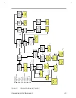
Page 185: ...Disassembly and Unit Replacement 4 5 Figure 4 3 Disassembly Sequence Flowchart ...
Page 209: ...B 2 Service Guide ...
Page 210: ...Exploded View Diagram B 3 ...

