1-
26
Service Guide
1.4.22
Charger
To charge the battery, place the battery pack inside the battery compartment and plug the AC adapter into
the notebook and an electrical outlet. The adapter has three charging modes:
•
Rapid mode
The notebook uses rapid charging when power is turned off and a powered AC adapter is connected to
it. In rapid mode, a fully depleted battery gets fully charged in approximately two hours.
•
Charge-in-use mode
When the notebook is in use with the AC adapter plugged in, the notebook also charges the battery
pack if installed. This mode will take longer to fully charge a battery than rapid mode. In charge-in-
use mode, a fully depleted battery gets fully charged in approximately six to eight hours.
•
Trickle mode
When the battery is fully charged, the adapter changes to trickle mode to maintain the battery charge
level. This prevents the battery from draining while the notebook is in use.
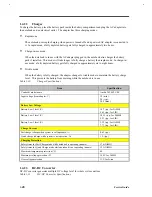
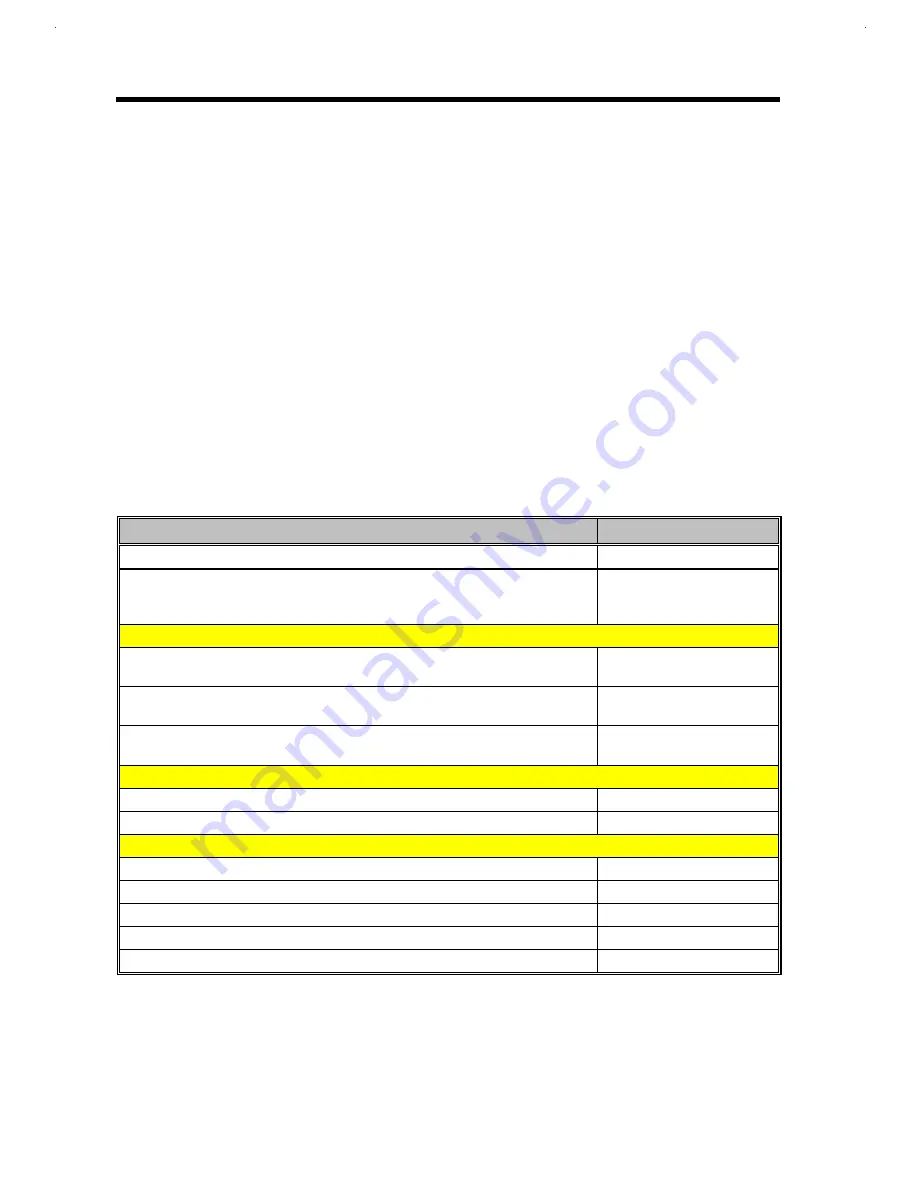
Table 1-30
Charger Specifications
Item
Specification
Vendor & model name
Ambit T62.062.C.00
Input voltage (from adapter, V)
19 (min.)
20 (typ.),
20.5 (max.)
Battery Low Voltage
Battery Low 1 level (V)
10.7 (typ., for NiMH)
8.65 (typ., for LIB)
Battery Low 2 level (V)
10.35 (typ., for NiMH)
8.23 (typ., for LIB)
Battery Low 3 level (V)
9.22 (typ., for NiMH)
7.73 (typ., for LIB)
Charge Current
Fast charge (charge when system is still operative, A)
0.65 (typ.)
Quick charge (charge while system is not operative, A)
1.9 (typ.)
Charging Protection
Safety timer for Fast Charge mode while notebook is operating (minute)
576 (NiMH)
Safety timer for Quick Charge mode while notebook is not operating (minute)
192 (NiMH)
Maximum temperature protection (ºC)
60
Maximum voltage protection (V)
16.2V for NiMH
Over voltage protection
13V for Li-ion
1.4.23
DC-DC Converter
DC-DC converter generates multiple DC voltage level for whole system unit use.
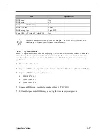
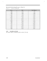
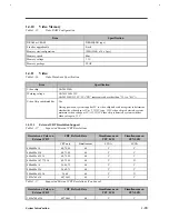
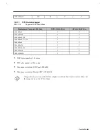
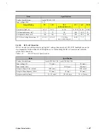
Table 1-31
DC-DC Converter Specifications
Summary of Contents for AcerNote Light 370P
Page 6: ...vi ...
Page 26: ...1 8 Service Guide Figure 1 5 Main Board Layout Bottom Side ...
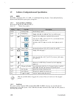
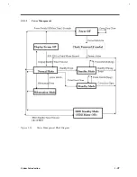
Page 49: ...System Introduction 1 31 1 5 1 3 Power Management Figure 1 14 Power Management Block Diagram ...
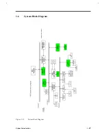
Page 55: ...System Introduction 1 37 1 6 System Block Diagram Figure 1 15 System Block Diagram ...
Page 64: ...Major Chips Description 2 7 2 2 5 Pin Diagram Figure 2 4 M1521 Pin Diagram ...
Page 99: ...2 42 Service Guide 2 5 3 Pin Diagram Figure 2 10 C T 65550 Pin Diagram ...
Page 117: ...2 60 Service Guide Figure 2 12 Functional block diagram CardBus Card Interface ...
Page 119: ...2 62 Service Guide Figure 2 14 PCI to CardBus terminal assignments ...
Page 135: ...2 78 Service Guide 2 7 3 Pin Diagram Figure 2 16 NS87336VJG Pin Diagram ...
Page 145: ...2 88 Service Guide 2 8 2 Pin Diagram Figure 2 17 YMF715 Block Diagram ...
Page 185: ...Disassembly and Unit Replacement 4 5 Figure 4 3 Disassembly Sequence Flowchart ...
Page 209: ...B 2 Service Guide ...
Page 210: ...Exploded View Diagram B 3 ...

