System Introduction
1-
27
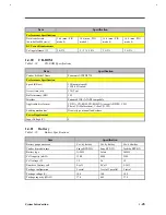
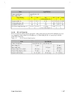
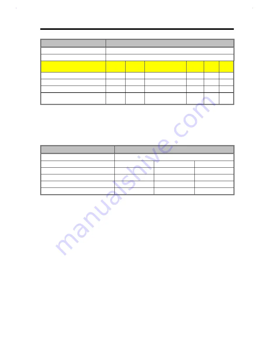
Item
Specification
Vendor & model name
Ambit T62.061.C.00
Input voltage (Vdc)
8~21
Output Rating
5V
3.3V
2.9V
(2.35/2.45/2.9/3.1V)
+12V
+6V
5VSB
Current (w/ load, A)
0~3.2
0~3.3
0~3.0
0~0.15
0~0.1
0.005
Voltage ripple (max., mV)
75
75
50
100
300
75
Voltage noise (max., mV)
100
100
100
200
500
100
OVP (Over Voltage Protection, V)
6.5~8.2
4.5~6.2
3.3~5.0 for
2.9/3.1/2.35V/2.45V
14~20
7~9
-
1.4.24
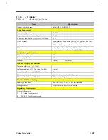
DC-AC Inverter
DC-AC inverter is used to generate very high AC voltage, then supply to LCD CCFT backlight use, and is
also responsible for the control of LCD brightness. Avoid touching the DC-AC inverter area while the
system unit is turned on.
Table 1-32
DC-AC Inverter Specifications
Item
Specification
Vendor & model name
Ambit T62.066.C.00 / Ambit T62.064.C.00
Input voltage (V)
7.3 (min.)
-
20 (max.)
Input current (mA)
-
420 (typ.)
550 (max.)
Output voltage (Vrms, no load)
1000 (min.)
-
1500 (max.)
Output voltage frequency (kHz)
25 (min.)
42 (typ.)
60 (max.)
Output current (mArms)
1.5~5.5 (min.)
2.0~6.0 (typ.)
2.5~6.5 (max.)
Summary of Contents for AcerNote Light 370P
Page 6: ...vi ...
Page 26: ...1 8 Service Guide Figure 1 5 Main Board Layout Bottom Side ...
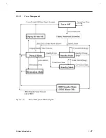
Page 49: ...System Introduction 1 31 1 5 1 3 Power Management Figure 1 14 Power Management Block Diagram ...
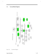
Page 55: ...System Introduction 1 37 1 6 System Block Diagram Figure 1 15 System Block Diagram ...
Page 64: ...Major Chips Description 2 7 2 2 5 Pin Diagram Figure 2 4 M1521 Pin Diagram ...
Page 99: ...2 42 Service Guide 2 5 3 Pin Diagram Figure 2 10 C T 65550 Pin Diagram ...
Page 117: ...2 60 Service Guide Figure 2 12 Functional block diagram CardBus Card Interface ...
Page 119: ...2 62 Service Guide Figure 2 14 PCI to CardBus terminal assignments ...
Page 135: ...2 78 Service Guide 2 7 3 Pin Diagram Figure 2 16 NS87336VJG Pin Diagram ...
Page 145: ...2 88 Service Guide 2 8 2 Pin Diagram Figure 2 17 YMF715 Block Diagram ...
Page 185: ...Disassembly and Unit Replacement 4 5 Figure 4 3 Disassembly Sequence Flowchart ...
Page 209: ...B 2 Service Guide ...
Page 210: ...Exploded View Diagram B 3 ...

