background image

51

6

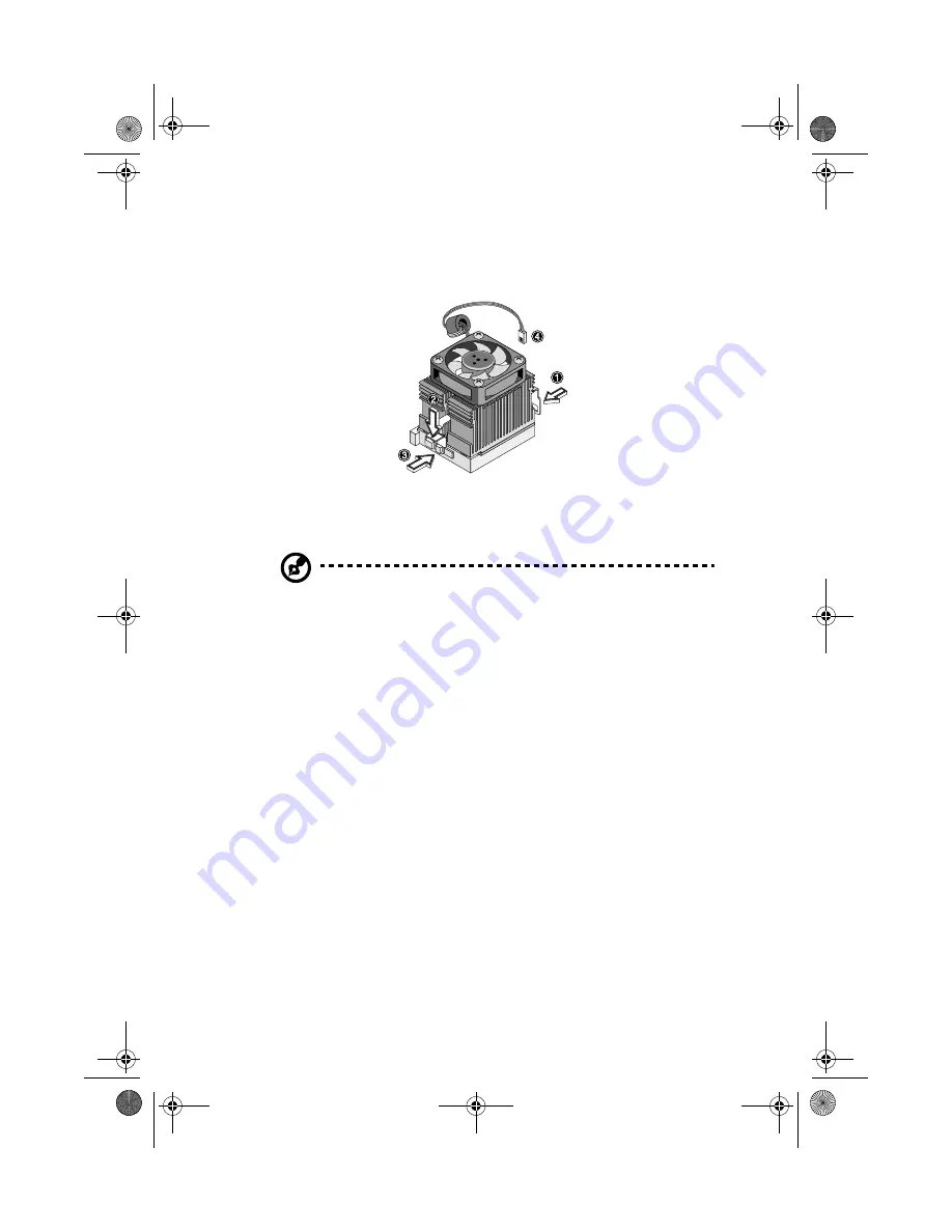
Attach one side of the fan/heatsink metal bracket to the CPU 
socket and then gently push down the other side of the metal 
bracket until it locks in place. 

7

Connect the 3-pin and 2-pin fan/heatsink cables to the system 
board.  Refer to “Mainboard” on page 45 for the location of the 
fan/heatsink connectors.

Note: 

The heatsink becomes very hot when the system is on.  

NEVER touch the heatsink with any metal or with your hands.

8

Reinstall the housing cover as instructed on page 43.

APSC-ug-en.book Page 51 Friday, October 5, 2001 9:39 AM

Summary of Contents for AcerPower Sc

Page 1: ...AcerPower SC User s guide APSC ug en book Page i Friday October 5 2001 9 39 AM ...

Page 2: ...r All correspondense concerning your unit should include the serial number model number and purchase information No part of this publication may be reproduced stored in a retrieval system or transmitted in any form or by any means electronic mechanical photocopy recording or otherwise without the prior written permission of Acer Incorporated Model Number _________________________________ Serial Nu...

Page 3: ...re of the following measures Reorient or relocate the receiving antenna Increase the separation between the device and receiver Connect the device into an outlet on a circuit different from that to which the receiver is connected Consult the dealer or an experienced radio television technician for help Notice Shield cables All connections to other computing devices must be made using shielded cabl...

Page 4: ...eived including interference that may cause undesired operation Notice Canadian users This Class B digital apparatus meets all requirements of the Canadian Interference Causing Equipment Regulations Remarque à l intention des utilisateurs canadiens Cet appareil numérique de la classe B respected toutes les exigences du Règlement sur le matériel brouilleur du Canada APSC ug en book Page iv Friday O...

Page 5: ...ted from the type of power indicated on the marking label If you are not sure of the type of power available consult your dealer or local power company 7 Do not allow anything to rest on the power cord Do not locate this product where persons will walk on the cord 8 If an extension cord is used with this product make sure that the total ampere rating of the equipment plugged into the extension cor...

Page 6: ...the product exhibits a distinct change in performance indicating a need for service f Replace the battery with the same type as the product s battery we recommend Use of another battery may present a risk of fire or explosion Refer battery replacement to a qualified serviceman 13 Warning Batteries may explode if not handled properly Do not disassemble or dispose of them in fire Keep them away from...

Page 7: ...LASER PRODUCT CAUTION INVISIBLE LASER RADIATION WHEN OPEN AVOID EXPOSURE TO BEAM Lithium battery statement CAUTION Danger of explosion if battery is incorrectly replaced Replace only with the same or equivalent type recommended by the manufacturer Discard used batteries according to the manufacturer s instructions APSC ug en book Page vii Friday October 5 2001 9 39 AM ...

Page 8: ...viii APSC ug en book Page viii Friday October 5 2001 9 39 AM ...

Page 9: ...eys 15 Mouse 16 Disk drives 17 3 5 inch floppy disk drive 17 CD ROM drive 17 Hard disk drive 19 3 Setting up your computer 21 Arranging a comfortable work area 23 Adjusting your chair 23 Positioning your PC 23 Positioning your monitor 23 Positioning your keyboard 24 Positioning your mouse 24 Connecting peripherals 25 Mouse 25 USB Keyboard 26 Monitor 27 Power cable 28 Connecting options 29 Printer ...

Page 10: ...t installation instructions 40 Opening your computer 41 Removing the cover 41 Replacing the cover 43 Mainboard 45 CPU frequency table 47 Installing additional memory 48 Installing a DIMM 48 Removing a DIMM 49 Reconfiguring your computer 49 Upgrading the CPU 50 Replacing the hard disk 52 Installing an expansion card 57 APSC ug en book Page x Friday October 5 2001 9 39 AM ...

Page 11: ...1 Overview APSC ug en book Page 1 Friday October 5 2001 9 39 AM ...

Page 12: ...This chapter gives an overview of the product and the peripherals that come with it It also contains tips on how to take care of your computer APSC ug en book Page 2 Friday October 5 2001 9 39 AM ...

Page 13: ...computer Carefully unpack the carton and remove the contents If any of the following items are missing or damaged contact your dealer immediately AcerPower SC USB keyboard Mouse Power cable User s guide Other user documentation and third party software APSC ug en book Page 3 Friday October 5 2001 9 39 AM ...

Page 14: ...d and any cables away from personal traffic When unplugging the power cord do not pull on the cord itself but pull on the plug The total ampere rating of the equipment plugged in should not exceed the ampere rating of the cord if you are using an extension cord Also the total current rating of all equipment plugged into a single wall outlet should not exceed the fuse rating Check the documentation...

Page 15: ...cover To clean your monitor Make sure that you keep your screen clean For cleaning instructions refer to the documentation that came with your monitor When to contact a service technician If you dropped and damaged the computer If liquid has been spilled into the computer If the computer is not operating normally APSC ug en book Page 5 Friday October 5 2001 9 39 AM ...

Page 16: ...1 Overview 6 APSC ug en book Page 6 Friday October 5 2001 9 39 AM ...

Page 17: ...2 System tour APSC ug en book Page 7 Friday October 5 2001 9 39 AM ...

Page 18: ...This chapter discusses the features and components of your computer APSC ug en book Page 8 Friday October 5 2001 9 39 AM ...

Page 19: ...ity Enhanced IDE hard disk Multimedia Integrated 128 bit 2D 3D graphics accelerator embedded in SiS630ET chipset Integrated 3D positional audio controller embedded in SiS630ET chipset Audio in Line in Audio out Line out Mic in and Game MIDI interfaces Connectivity PS 2 mouse and USB keyboard interface One serial port one parallel port and one VGA port Universal Serial Bus USB ports Integrated 10Ba...

Page 20: ...adphone Earphone port 7 Power LED 2 Increase decrease volume 8 LAN LED 3 CD ROM LED 9 Power button 4 CD ROM tray 10 3 5 inch floppy disk drive eject button 5 Stop Eject button 11 3 5 inch floppy disk drive 6 Skip Forward button 12 3 5 inch floppy disk drive LED APSC ug en book Page 10 Friday October 5 2001 9 39 AM ...

Page 21: ... main power switch 10 Parallel port 2 Voltage selector 11 VGA Monitor port 3 System power socket 12 Speaker out Line out port 4 Fan 13 Game MIDI port 5 PS 2 keyboard port 14 Line in port 6 PS 2 mouse port 15 Microphone in port 7 LAN port 16 Add on brackets 8 USB ports 17 Optional USB ports These two optional USB ports are only available in some regions 9 Serial 2 port APSC ug en book Page 11 Frida...

Page 22: ...e cursor keys two Windows keys and twelve function keys No Description 1 Programmable keys 2 Internet Suspend keys 3 Multimedia keys 4 Volume Mute nob 5 Scroll lock key 6 Num lock key 7 Cursor keys 8 Application key 9 Windows keys 10 Caps lock key 11 Function keys APSC ug en book Page 12 Friday October 5 2001 9 39 AM ...

Page 23: ...s The multimedia keys Allow you to play pause stop step forward or step back a song or movie conveniently using your keyboard Icon Key Description Email Launches your email application Web browser Launches your current default browser Suspend Resume Press this button to put the system to sleep Press again to wake the system up Icon Key Description Play Pause Press to start playing an audio or vide...

Page 24: ...ggle on and off to switch between two functions Backward Press to skip backward to the previous file and start playing Lock Key Description Caps Lock When activated all alphabetic characters typed appear in uppercase same function as pressing Shift letter Num Lock When activated the keypad is set to numeric mode i e the keys function as a calculator complete with arithmetic operators such as and S...

Page 25: ...l functions such as Windows Tab Activate the next Taskbar button Windows E Explore My Computer Windows F Find Document Windows M Minimize All Shift Windows M Undo Minimize All Windows R Display Run dialog box Application key Opens the applications context menu same function as clicking the right button of the mouse APSC ug en book Page 15 Friday October 5 2001 9 39 AM ...

Page 26: ...s added to provide easier scrolling capability By simply moving the wheel with your index finger you can quickly move through multiple pages lines or windows The wheel may also function as a third button allowing you to quickly click or double click an icon or a selected item For information on how to clean your mouse see To clean your mouse on page 5 PS 2 Mouse USB Mouse Note If you are left hand...

Page 27: ... is on Write protect your diskettes to prevent accidental erasure To do this slide the write protect tab to the write protect position When you put a label on a 3 5 inch diskette make sure that the label is properly attached flat on the surface and within the labeling area area with a slight surface depression on the diskette An improperly attached label may cause a diskette to get stuck in a driv...

Page 28: ...t a CD into your computer s CD ROM drive 1 Gently push the eject button located on the front panel 2 Insert the CD Make sure that the label or title side of the CD is facing upward Caution Hold the CD by the edges to avoid leaving smudges or fingerprints APSC ug en book Page 18 Friday October 5 2001 9 39 AM ...

Page 29: ...n handling CDs always hold them by the edges to avoid smudges or fingerprints When cleaning CDs use a clean dust free cloth and wipe in a straight line from the center to the edge Do not wipe in a circular motion Clean your CD ROM drive periodically You may refer to the Cleaning Kit for instructions Cleaning Kits can be purchased in any computer or electronics shop Hard disk drive Your computer is...

Page 30: ...2 System tour 20 APSC ug en book Page 20 Friday October 5 2001 9 39 AM ...

Page 31: ...3 Setting up your computer APSC ug en book Page 21 Friday October 5 2001 9 39 AM ...

Page 32: ...This chapter contains step by step instructions on how to set up your computer and connect additional peripherals APSC ug en book Page 22 Friday October 5 2001 9 39 AM ...

Page 33: ... that you can sit on it with your thighs parallel to the floor and your feet resting flat on the floor Rest your body on the chair back Your torso works harder to maintain balance if you do not rest your body on the chair back Positioning your PC Do not put your computer near any equipment that might cause electromagnetic or radio frequency interference such as radio transmitters televisions copy ...

Page 34: ...should be relaxed Then try typing with a light touch If you feel any shoulder or neck strain stop for a while and check your posture Position your keyboard in front of your monitor Putting your keyboard beside your monitor will make you turn your head while you type which could add tension to your neck muscles that may later result in neck strain Positioning your mouse The mouse should be placed o...

Page 35: ...four things to connect the mouse the USB keyboard the monitor and the power cable Mouse Plug the mouse cable into the PS 2 mouse port or USB port located on the rear panel of your computer Connecting the PS 2 mouse Connecting the USB mouse APSC ug en book Page 25 Friday October 5 2001 9 39 AM ...

Page 36: ...3 Setting up your computer 26 USB Keyboard Plug the USB keyboard cable into the USB port located on the rear panel of your computer APSC ug en book Page 26 Friday October 5 2001 9 39 AM ...

Page 37: ...simply plug the monitor cable into the external monitor port located on the rear panel of your computer Note Refer to the monitor manual for additonal instructions and information APSC ug en book Page 27 Friday October 5 2001 9 39 AM ...

Page 38: ... voltage setting switch located on the rear panel of your computer If they don t match change your computer s voltage setting according to your area s voltage range Plug the power cable into the power cable socket located on the rear panel of your computer Then plug the other end of the power cable into a power outlet APSC ug en book Page 28 Friday October 5 2001 9 39 AM ...

Page 39: ...nter cable into the parallel port located on the rear panel of your computer To connect a serial printer plug the printer cable into either serial port 1 or serial port 2 located on the rear panel of your computer See Rear panel on page 11 for the location of the serial ports APSC ug en book Page 29 Friday October 5 2001 9 39 AM ...

Page 40: ...ea Network LAN using a network cable To do so simply plug the network cable into the network port on the rear panel of your computer Note Consult your operating system manual for information on how to configure your network setup APSC ug en book Page 30 Friday October 5 2001 9 39 AM ...

Page 41: ...in your system Contact your dealer for more information Set up your modem connection by plugging the telephone line and handset into their correspond ports on the rear panel of your computer Refer to the figure below for the connections APSC ug en book Page 31 Friday October 5 2001 9 39 AM ...

Page 42: ...features Plug the devices in as follows microphone connect to Mic in port speakers earphones headphones connect to Audio out Line out port external CD player connect to Audio in Line in port joystick connect to Game MIDI port Refer to the figure below for the connections Note For information on how to configure the multimedia devices consult the documentation that came with each device APSC ug en ...

Page 43: ...ctions can be eliminated Your computer comes with two USB ports located on the rear panel These ports allow you to connect additional serial devices to your computer without using up its system resources To connect a USB device simply plug the device cable into either of the USB ports Note Most USB devices have a built in USB port which allows you to daisy chain other devices APSC ug en book Page ...

Page 44: ...wer cable you are now ready to turn the computer on and get to work To turn on your computer 1 Turn on all peripherals connected to your computer such as the monitor printer fax speakers etc 2 Locate and turn on the main power switch on the rear panel of your computer APSC ug en book Page 34 Friday October 5 2001 9 39 AM ...

Page 45: ...shes booting it is now ready for use Important Make sure that the power cable is properly plugged into an electrical outlet If you are using a power strip or an AVR Auto Voltage Regulator make sure that it is plugged in and turned on APSC ug en book Page 35 Friday October 5 2001 9 39 AM ...

Page 46: ...s connected to your computer and then press the power button for at least four seconds Quickly pressing the button may put the computer in Suspend mode only Note You do not need to turn off the main power switch every time you turn off your computer Turn off the main power switch only if you will not use your computer for a long time or your computer needs servicing APSC ug en book Page 36 Friday ...

Page 47: ...4 Upgrading your computer APSC ug en book Page 37 Friday October 5 2001 9 39 AM ...

Page 48: ...ontains instructions on how to upgrade your computer and basic information about your system board that you will find helpful when performing the upgrade process APSC ug en book Page 38 Friday October 5 2001 9 39 AM ...

Page 49: ...out any procedure requiring ESD protection Preinstallation instructions Always observe the following before you install any component 1 Turn off your computer and all the peripherals connected to it before opening it Then unplug all cables from the power outlets 2 Open your computer according to the instructions on Opening your computer on page 41 3 Follow the ESD precautions described above befor...

Page 50: ... the step by step instructions in their respective sections 2 Make sure you have set all the required jumpers See Mainboard on page 45 for the correct jumper settings 3 Replace any expansion boards or peripherals that you removed earlier 4 Replace the computer cover 5 Connect the necessary cables and turn on your computer APSC ug en book Page 40 Friday October 5 2001 9 39 AM ...

Page 51: ...o open your computer before you can install additional components See the following section for instructions Removing the cover 1 Turn off the system power and unplug all cables 2 Place the system unit on a flat steady surface 3 Remove the four screws from the rear panel Set the screws aside You will need them when replacing the housing cover APSC ug en book Page 41 Friday October 5 2001 9 39 AM ...

Page 52: ...4 Upgrading your computer 42 4 Push the housing cover slightly backward then pull it upward to remove it from the chassis APSC ug en book Page 42 Friday October 5 2001 9 39 AM ...

Page 53: ...43 Replacing the cover 1 Replace the housing cover APSC ug en book Page 43 Friday October 5 2001 9 39 AM ...

Page 54: ...4 Upgrading your computer 44 2 Secure the housing cover with the necessary screws APSC ug en book Page 44 Friday October 5 2001 9 39 AM ...

Page 55: ...d jumpers of the mainboard Refer to the table for a brief description of each connectors and jumpers The mainboard becomes accessible once you open your computer It should look like the figure shown below APSC ug en book Page 45 Friday October 5 2001 9 39 AM ...

Page 56: ...D connector CN12 FDD connector CN13 HDD LED connector CN16 Fax voice modem connector CN18 Wake on LAN c onnector CN20 RF connector CN21 Slim CD ROM connector CN22 Optional USB ports CN23 Audio in connector JP1 1 2 Disable onboard Codec 2 3 Enable onboard Codec JP2 Power LED connector JP3 1 2 and 4 5 4M flash ROM 2 3 and 5 6 2M flash ROM JP4 Reset connector JP5 Intrusion JP6 LAN LED connector APSC ...

Page 57: ...t CN21 as slave 2 3 set CN21 as Master S4 S3 S2 S1 CPU SDRAM 0 0 0 0 66 100 0 0 0 1 100 100 0 0 1 0 150 100 0 0 1 1 133 100 0 1 0 1 100 133 0 1 1 0 100 150 0 1 1 1 133 133 1 0 0 0 66 66 Connector Description APSC ug en book Page 47 Friday October 5 2001 9 39 AM ...

Page 58: ... MHz SDRAM However they cannot be used at the same time in a computer Please contact your dealer for qualified DIMM vendors Caution Do not use both PC 100 100 MHz and PC 133 133 MHz SDRAM together Such a combination might cause your system to malfunction Each of the DIMM sockets is independent from the others This independence allows you to install DIMMs with different capacities to form different...

Page 59: ...ss the holding clips on both sides of the socket outward to release the DIMM 2 Gently pull the DIMM out of the socket Reconfiguring your computer Your computer automatically detects the amount of memory installed Run Setup to view the new value for total system memory and make a note of it For more information about the Setup Utility refer to the Setup Utility in the online manual APSC ug en book ...

Page 60: ...teps to upgrade your CPU 1 Remove the cover as shown on page 41 2 Disconnect the 3 pin and 2 pin fan heatsink cables from the system board 3 Unhook one side of the fan heatsink metal bracket and gently lift it before removing the other side 4 Gently push the socket lever down to release the lever and then pull it up to remove the CPU 5 Insert the new CPU Make sure that pin 1 indicated by a notched...

Page 61: ...ect the 3 pin and 2 pin fan heatsink cables to the system board Refer to Mainboard on page 45 for the location of the fan heatsink connectors Note The heatsink becomes very hot when the system is on NEVER touch the heatsink with any metal or with your hands 8 Reinstall the housing cover as instructed on page 43 APSC ug en book Page 51 Friday October 5 2001 9 39 AM ...

Page 62: ... the hard disk Follow these steps to replace the hard disk drive 1 Remove the cover as shown on page 41 2 Disconnect all cables connected to the hard disk and 3 5 inch floppy disk drives APSC ug en book Page 52 Friday October 5 2001 9 39 AM ...

Page 63: ...53 3 Remove the 3 5 inch drive frame from the housing by pressing the tab on top and pivoting the frame outward APSC ug en book Page 53 Friday October 5 2001 9 39 AM ...

Page 64: ...e and pull out the hard disk drive 5 Install a new 3 5 inch hard disk drive and secure it with the fours screws that you have removed previously 6 Reinstall the frame into the housing as in the following figure a Align the frame with the notch APSC ug en book Page 54 Friday October 5 2001 9 39 AM ...

Page 65: ...55 b Pivot the frame toward the housing until the tab clicks into place ...

Page 66: ... and power cables Note Make sure that the other ends of the floppy disk drive cables are connected to their corresponding connectors on the system board 7 Reinstall the housing cover as instructed on page 43 APSC ug en book Page 56 Friday October 5 2001 9 39 AM ...

Page 67: ...system board 3 Remove the bracket on the housing opposite the selected empty slot 4 Remove the PCI card from its protective packaging 5 Align then insert the PCI card into the slot Make sure that the card is properly seated 6 Secure the card to the housing with a screw 7 Reinstall the housing cover see page 43 When you turn on the system BIOS automatically detects and assigns resources to the PCI ...

Page 68: ...4 Upgrading your computer 58 APSC ug en book Page 58 Friday October 5 2001 9 39 AM ...

Reviews: