Chapter 4
67
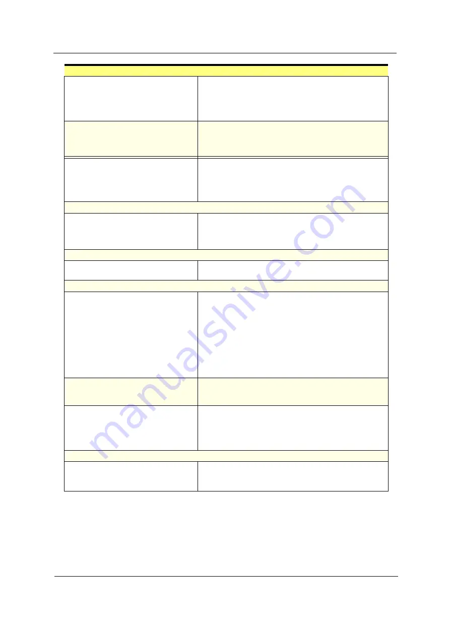
CD/DVD-ROM drive cannot load or eject
when the system is turned on and its
eject button is pressed and held.
1. Disconnect all cables from CD/DVD-ROM drive except
power cable, then press eject button to try to unload the
disk.
2. CD/DVD-ROM drive power.
3. CD/DVD-ROM drive
CD/DVD-ROM drive does not read and
there are no messages are displayed.
1. CD may have dirt or foreign material on it. Check with a
known good disc.
2. Ensure the CD/DVD-ROM driver is installed properly.
3. CD/DVD-ROM drive.
CD/DVD-ROM drive can play audio CD
but no sound output.
1. Ensure the headphone jack of the CD/DVD-ROM has an
output.
2. Turn up the sound volume.
3. Speaker power/connection/cable.
4. CD/DVD-ROM drive.
Real-Time Clock
Real-time clock is inaccurate.
1. Ensure the information in the
Date and Time
of BIOS
Setup is set correctly.
2. RTC battery.
3. System board
Audio
Audio software program invokes but no
sound comes from speakers.
1. Speaker power/connection/cable.
Modem
Modem ring cannot wake up system
from suspend mode.
1. Ensure the
Modem Ring Indicator
in BIOS Setup or
Power Management
is set to
Enabled
.
2. If PCI modem card is used, reinsert the modem card to
PCI slot firmly or replace the modem card.
3. If ISA modem card is used, ensure the modem ring-in
cable from the modem card to system board is connected
properly.
4. In Win 98, ensure the telephone application is configured
correctly for your modem and set to receive messages
and/or fax.
Data/fax modem software program
invokes but cannot receive/send data/
fax
1. Ensure the modem card is installed properly.
Fax/voice modem software program
invokes but has no sound output. (Data
files are received normally; voice from
modem cannot be produced, but system
sound feature works normally.)
1. Ensure the modem voice-in cable from modem adapter
card to system board
Video and Monitor
Video memory test failed.
Video adapter failed.
1. Remove all non-factory-installed cards.
2. Load default settings (if screen is readable).
3. System board
Error Symptom
Action/FRU
Summary of Contents for AcerPower SV
Page 15: ...8 Chapter 1 Block Diagram ...
Page 16: ...Chapter 1 9 Main Board Layout ...
Page 29: ...22 Chapter 1 ...
Page 49: ...42 Chapter 2 ...
Page 77: ...70 Chapter 4 ...
Page 86: ...80 Chapter 6 AcerPower SV Exploded Diagram ...


