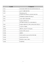
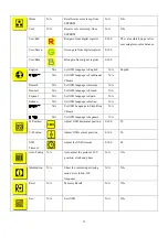
background image


  13


Symbol 

Component 

U301 S524A40X21/BR24C02F-WE2/AT24C02/HT24LC02 

U401 

gm2121 (SMD PQFP208) 

U402 

Flash Memory 1M 
W39F010-70/A290011TL-70/S29C51001T-90J 

U403 EEPROM 

S524A60X81/HT24LC04 

U701 

Audio AMP IC LM4843MH 

U801 Regulator 

SMD 

TO-263 

AP1086K33A/LM1117S3.3/FAN1086M33X 

U802 

Regulator SMD TO-252 SP1117D25A/LM1117DT-2.5 

X401 Crystal 

14.318MHz 

CN201 

S8B-ZR (connect I/F and keypad) 

CN301 

D-SUB 15PIN connector 

CN401 S4BPH-J 

CN601 

Pitch 1mm FPC connector FPC1S30T11R01 

CN701 

Audio Jack ST-413-06 

CN702 

B5B-PH-K (Audio control) 

CN801 B12B-PH-K 


Summary of Contents for AL1713

Page 1: ...Acer AL1713 Service Guide Service guide files and updates are available on the CSD web for more information Please refer to http csd acer com tw ...

Page 2: ...ect to the contents hereof and specifically disclaims any warranties of merchantability or fitness for any particular purpose Any Acer Incorporated software described in this manual is sold or licensed as is Should the programs prove defective following their purchase the buyer and not Acer Incorporated its distributor or its dealer assumes the entire cost of all necessary servicing repair and any...

Page 3: ...bits and pieces of additional information related to the current topic WARNING Alerts you to any damage that might result from doing or not doing specific actions CAUTION Gives precautionary measures to avoid possible hardware or software problems IMPORTANT Reminds you to do specific actions relevant to the accomplishments of procedures ...

Page 4: ...ll NOT be covered in this generic service guide In such cased please contact your regional offices or the responsible personnel channel to provide you with further technical details 2 Please not WHEN ORDER FRU PARTS that you should check the most up to date information available on your regional web or channel If for whatever reason a part number change is made it will not be noted in the printed ...

Page 5: ...eiving antenna 2 Increase the separation between the equipment and receiver 3 Connect the equipment into an outlet on a circuit different from that to which the receiver is connected 4 Consult the dealer or an experienced radio TV technician for help Notice 1 The changes or modifications not expressly approved by the party responsible for compliance could void the user s authority to operate the e...

Page 6: ...purpose of the grounded plug Unplug the unit during a lightning storm or when it will not be used for long periods of time This will protect the monitor from damage due to power surges Do not overload power strips and extension cords Overloading can result in fire or electric shock Never push any object into the slot on the monitor cabinet It could short circuit parts causing a fire or electric sh...

Page 7: ...MAIN BOARD DIAGRAM 10 Software Flow Chart 11 MONITOR INTERFACE BOARD PCB LAYOUT 12 FRONT BEZEL 14 BACK VIEW 15 OPERATION INSTRUCTIONS 16 ADJUSTING THE MONITOR 18 MACHINE ASSEMBLY 22 TROUTROUBLESHOOTING 26 FRU Field Replaceable Unit LIST 33 SHEMATIC DIAGRAM 38 Table of Contents ...

Page 8: ...6bits FRC Max Pixel Clock 135MHz Max Resolution 1280 x 1024 75Hz Plug Play VESA DDC 1 2B EPA ENGERGY STAR ON MODE 36W OFF MODE 5W Audio Output Rated Power 2 0W rms channel Input Connector D Sub 15pin Three Pronged Pin Input Video Signal Analog 0 7Vp p Standard 75 OHM Positive Analog Only Model Horizontal 337 920mm Maximum Screen Size Vertical 270 336mm Power Source 100 240VAC 50 60Hz Environmental...

Page 9: ...ET TIMING TABLE Standard Resolution Horizontal Frequency KHz Vertical Frequency Hz 640 x 480 31 469 60 000 640 x 480 37 861 72 809 VGA 640 x 480 37 500 75 000 800 x 600 35 156 56 250 800 x 600 37 879 60 317 800 x 600 48 077 72 188 SVGA 800 x 600 46 875 75 000 1024 x 768 48 363 60 004 1024 x 768 56 476 70 069 XGA 1024 x 768 60 023 75 029 1280 x 1024 63 981 60 020 SXGA 1280 x 1024 79 976 75 025 640 ...

Page 10: ...d power section supplies 12V 5V for Inverter and Interface board used The inverter section drives the backlight of panel and the DC DC conversion Video signal DDC Inverter power board Including AC DC Power supply and inverter Interface board Keypad board Flat Panel and CCFL Backlight Host Computer RS232 Connector for debug used AC IN 90V 264V ...

Page 11: ...DA SCL Hsync Vsync RGB LCD Interface CON501 Scalar gmZAN3 L Include ADC PLL OSD LVDS transmitter U401 MCU SM59264 U402 D Sub Connector CON301 EEPROM 24C02 U300 SCL_VGA SDA_VGA EEPROM 24C08 or 24C04 U201 OSD Control CN201 U300 ...

Page 12: ... 4 Get the user value and mode setting from EEProm 5 Are the factory key pressed 6 Enter factory mode 7 Check the analog port are there any signal coming 8 Display No Signal message 9 Enter sleep mode 10 Wake up the scalar 11 Program the scalar to be able to show the coming mode 12 Turn on the LED and set it to green color 13 Process the OSD display 14 Read the keyboard Is any key pressed ...

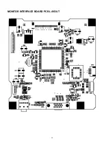
Page 13: ...12 MONITOR INTERFACE BOARD PCB LAYOUT ...

Page 14: ...60X81 HT24LC04 U701 Audio AMP IC LM4843MH U801 Regulator SMD TO 263 AP1086K33A LM1117S3 3 FAN1086M33X U802 Regulator SMD TO 252 SP1117D25A LM1117DT 2 5 X401 Crystal 14 318MHz CN201 S8B ZR connect I F and keypad CN301 D SUB 15PIN connector CN401 S4BPH J CN601 Pitch 1mm FPC connector FPC1S30T11R01 CN701 Audio Jack ST 413 06 CN702 B5B PH K Audio control CN801 B12B PH K ...

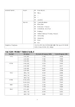
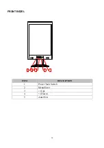
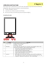
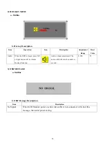
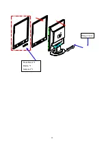
Page 15: ...14 FRONT BEZEL ITEM DESCRIPTION 1 Power Tack Switch 2 Menu Enter 3 Up 4 Down 5 Auto Exit ...

Page 16: ...15 BACK VIEW ITEM DESCRIPTION 1 Three pronged power cord 2 VGA Cable with blue connector compliance with PC99 3 Audio cable ...

Page 17: ...LED Orange Off mode 2 Menu Enter Activate OSD menu when OSD is off or activate de activate adjustment function when OSD is ON or Exit OSD menu when in Volume Adjust OSD status 3 1 Activates the volume control when the OSD is OFF 2 Navigate through adjustments icons when OSD is ON 3 Adjust a function when function is activated 4 1 Activates the volume control when the OSD is OFF 2 Navigate through ...

Page 18: ...andy if you ever have to ship your monitor For maximum protection repackage your monitor as it was originally packed in the factory To keep the monitor looking new periodically clean it with a soft cloth Stubborn stains may be removed with a cloth lightly dampened with a mild detergent solution Never use strong solvents such as thinner benzene or abrasive cleaners since these will damage the cabin...

Page 19: ...ntrast from digital register 0 100 50 Brightness Backlight Adjustment 0 100 100 Phase Adjust picture phase to reduce horizontal line noise 0 100 Do auto config Clock Adjust picture clock to reduce vertical line noise 0 100 Do Auto Config H Position Adjust picture horizontal position 0 100 Do Auto Config V Position Adjust picture vertical position 0 100 Do Auto Config ...

Page 20: ...SD language to German N A Francais N A Set OSD language to French N A Espanol N A Set OSD language to Spain N A Italiano N A Set OSD language to Italian N A 簡體中文 N A Set OSD Language to Simplified Chinese N A 日本語 N A Set OSD language to Japanese N A English H Position Adjust OSD horizontal position 0 100 50 V Position Adjust OSD vertical position 0 100 50 OSD Timeout Adjust the OSD timeout 0 100 4...

Page 21: ... is closed press left or right button will be volume Hot key Function Audio volume adjustment The audio will be Mute when audio is set to 0 0 100 50 3 OSD MESSAGE a Outline b OSD Message Description Item Description No Signal When LCD Monitor power on but video cable is not connected will show this message then enter power saving ...

Page 22: ...s monitor meets the Green monitor standards as set by the Video Electronics Standards Association VESA and or the United States Environmental Protection Agency EPA and the Swedish Confederation Employees NUTEK This feature is designed to conserve electrical energy by reducing power consumption when there is no video input signal present When there is no video input signal this monitor following a ...

Page 23: ...surface when mounting or removing the base 3 Wear gloves Chassis 1 Front bezel 1 Button 1 Indicator 1 Control board 1 PW3x6 M ZN CC Back cover 1 B3x8 T6 black 2 Hinge cover 1 Speaker L 1 Speaker R 1 B3x8 T6 black Base Stand plate 1 F3x8 T6 ZN 6 Interface board 1 PW3x6 MΔ S TITE ZN 3 CPT Panel 1 PW3x6 M ZN CC 8 Cord keep 2 FFC 30pin 1 TAPE 3M 5491 19x60mm 1 POW INV board 1 PW3x6 MΔ S TITE ZN 3 EMI ...

Page 24: ...C 30pin 1 TAPE 3M 5491 19x60mm 1 Out port PW3x6 MΔ S TITE ZN 3 F3x8 MΔ S TITE NI 2 POW INV board 1 PW3x6 MΔ S TITE ZN 3 B BW4x6 M ZN 2 Interface board 1 PW3x6 MΔ S TITE ZN 3 Bolt 4 40 NI 2 Gasket 20x10x3mm 4 EMI shield 1 PW3x6 MΔ S TITE ZN 5 Mounting bracket F4x6 M ZN 4 Hinge L 1 Hinge R 1 F4x6 M ZN 4 ...

Page 25: ...24 Back cover 1 B3x8 T6 black 2 Speaker L 1 Speaker R 1 B3x8 T6 black 4 Arm Stand 1 P 2FW4x22 M ZN 4 Rubber 4 Base cover 1 Stand plate 1 F3x8 T6 ZN 6 ...

Page 26: ...25 Front Bezel 1 Button 1 Indicator 1 Hinge Cover ...

Page 27: ... in the analog circuit part if only some scale appears abnormal color that stand the problem happen in the digital circuit part If you check the H V position please use the crosshatch pattern This LCM support 20 timing modes if the input timing mode is out of specification the picture appears abnormally Auto Color Balance Press and together and plug in AC power cord at the same time at VGA cable i...

Page 28: ...301 13 14 separately Do the Hsync Vsync Signals exist in R304 R305 Do the Hsync Vsync Signals exist in U401 101 100 Is the frequency 14 318MHz at 102 of U401 Change U401 END Insert VGA Cable correctly Check R304 R305 Change R304 R305 Change X401 NO NO NO NO YES YES YES YES YES ...

Page 29: ...u Button Does OSD display Are there R G B signal in U401 135 131 127 Is there clock signal in U401 102 Check DC 5V OF CN601 1 2 3 Are there data out U401 48 57 64 73 Change U401 END Change FL301 FL302 FL303 Change X401 Check Q601 circuit YES YES YES YES YES NO NO NO NO ...

Page 30: ...me scale 2 5 If brightness uniform change Inverter or Panel 2 6 If you find the vertical line on the screen please change panel Color lost in some scale at 16 gray scale pattern Re insert the FFC Cable Change FFC Cable Change M B OK END OK END NO NO ...

Page 31: ...0 16V Is there DC12V DC5V at 6 8 of CN852 Is the voltage at C854 in the range of 127V 339V NO Check F850 D850 YES Is the voltage at 6 of U850 0 8V YES YES Is the voltage at 6 of T850 38V YES Check Q851 YES Check R855 R857 R852 NO Check R859 NO Check D853 D854 NO ...

Page 32: ...acklight cannot be turned on Is the voltage 12V at CN852 6 Check U1 Pin6 Voltage is 5V Check U1 Pin1 Voltage is high Check T1 or T2 Pin6 and Pin7 Open or Short Change T1 or T2 Check R1 Check U2 U3 YES YES YES YES NO NO LED Green No Raster ...

Page 33: ...MATION VGA Connector D Sub 15pin Pin Assignments Pin Symbol Pin Symbol Pin Symbol 1 Red 6 Red_GND 11 N C 2 Green 7 Green_GND 12 DDC_SDA 3 Blue 8 Blue_GND 13 HSYNC 4 N C 9 PC 5V 14 VSYNC 5 GND 10 N C 15 DDC_SCL Chapter 5 ...

Page 34: ...on available on your regional web or channel http aicsl acer com tw spl For whatever reasons a part number change is made it will not be noted in the printed Service Guide You MUST use the local FRU list provided by your regional Acer office to order FRU parts for repair and service of customer machines Note To scrap or to return the defective parts You should follow the local government ordinance...

Page 35: ...ss W WAS 2 M4 22 Zn XXXXXX S 1 29 30 28 Option Speaker 509212308100 509000000700 509476606100 509216308301 509216606100 509413308500 6 2 4 4 509146622100 503020000800 4 501010202201 501030200700 501120300200 501010202200 Identification No 1 1 1 1 Q t 1 Remark Cable Ties 98mm IMAC15 Clip Wire Speaker R L 23 25 26 24 No 22 Designation W SHIELDIN UL1007 24 Remark 511200000200 618100220020 43030050010...

Page 36: ...r Cover Hinge White Cover Hinge Black 501020201500 501020201501 Base Cover Cover Base White Cover Base Black 501020201600 501020201601 Stand Plate Plane stand 502170900100 Arm Stand Cover Arm stand white Cover Arm stand Black 501020201900 501020201901 Speaker Speaker 2W 4OHM P 40mm 618100200100 Back Cover Cover Back White w SPK Cover Back White w o SPK Cover Back Black w SPK Cover Back Black w o S...

Page 37: ...ol board w SPK PCBA Control board w o SPK 79020150000 Out Port Pocket I O W SPK Pocket I O w o SPK 502160200100 502160200110 Panel CLAA170EA02 631102070030 FFC FFC Cable Pitch 1mm 30P L 140mm 454040409010 Cord Keep CLIP WIRE 511100001300 Gasket 10x4x20mm 503060001600 Chassis Chassis 502090100600 Hinge L Hinge Left 502060400500 Hinge R Hinge Right 502060400600 HRN 5P 180mm HRN ASS Y 5P 180mm UL1007...

Page 38: ...300800020 Base Screw Screw F Cross T 3 8 Zn 509212308100 Inverter Board Screw Small Screw C Cross M3 6 S TITE Zn 509916306101 Inverter Board Screw Big Screw B Cross M4 6 Zn 509476606100 Interface Board Screw Screw C Cross M3 6 S TITE Zn 509916306101 ...

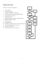
Page 39: ...38 SHEMATIC DIAGRAM Keypad Diagram Chapter 7 ...

Page 40: ...39 Interface Board Schematic ...

Page 41: ...40 ...

Page 42: ...41 ...

Page 43: ...42 ...

Page 44: ...43 ...

Page 45: ...44 ...

Page 46: ...45 POW INV Board Schematic ...

Page 47: ...46 ...

Reviews: