


22
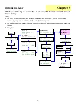
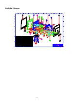
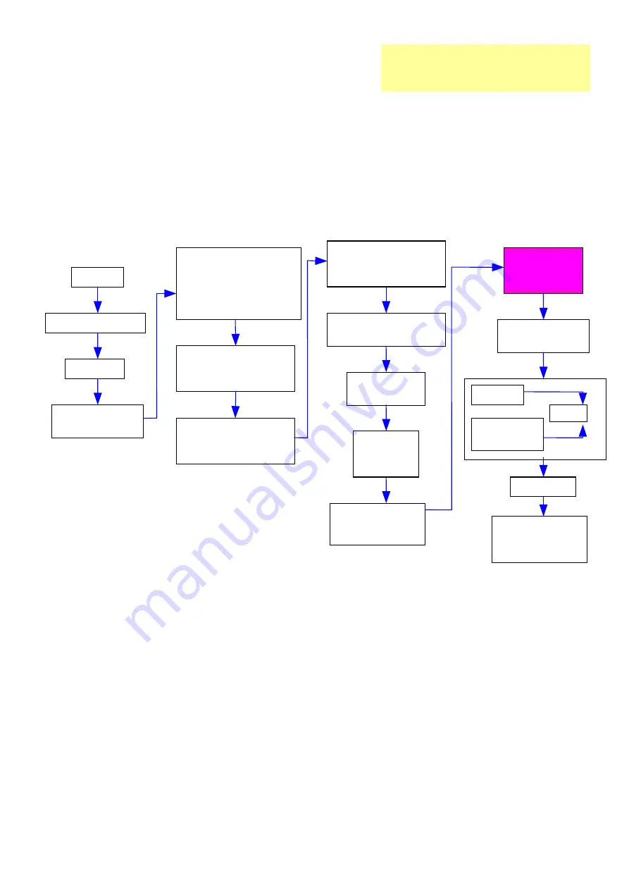
MACHINE ASSEMBLY
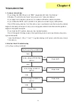
This chapter contains step-by-step procedures on how to assemble the monitor for maintenance and
troubleshooting.
NOTE:
1.
The screws for the different components vary in size. During the disassembly process, collect the screws with the
corresponding components to avoid mismatch when putting back the components.
2.
The monitor surface is susceptible to scratching! Therefore, lay the monitor on a soft surface when mounting or removing
the base.
3.
Wear gloves
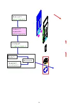
Chassis*1
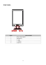
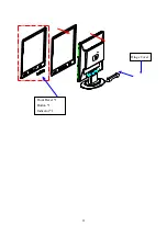
Front bezel*1
Button*1
Indicator*1
Control board*1
(PW3x6,M,ZN-CC)*
Back cover*1
(B3x8,T6,black)*2
Hinge cover*1
Speaker L*1
Speaker R*1
(B3x8,T6,black)*
Base
Stand plate*1
(F3x8,T6,ZN)*6
Interface board*1
(PW3x6,M
Δ,
S-TITE,ZN)*3
CPT Panel*1
(PW3x6, M, ZN-CC)*8
Cord keep*2
FFC (30pin)*1
TAPE, 3M#5491(19x60mm)*1
POW/INV board*1
(PW3x6,M
Δ,
S-TITE,ZN)*3
EMI shield*1
(PW3x6, M
∆
, S-TITE,ZN)*5
Mounting bracket
(F4x6, M, ZN)*4
Out port
(PW3x6,M
Δ,
S-TITE,ZN)*3
(F3x8, M
Δ,
S-TITE, NI)*2
Cable ties*1
Rubber*4
Arm Stand*1
(P/2FW4x22,M,ZN)*
Hinge L*1
Hinge R*1
(F4x6,M,ZN)*4
Gasket (20x10x3mm)*4
Chapter 3
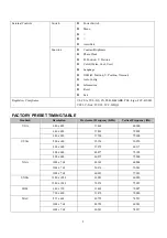
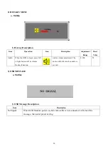
Summary of Contents for AL1713
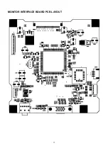
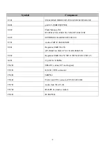
Page 13: ...12 MONITOR INTERFACE BOARD PCB LAYOUT ...
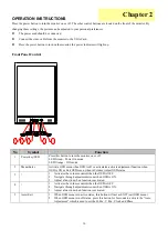
Page 15: ...14 FRONT BEZEL ITEM DESCRIPTION 1 Power Tack Switch 2 Menu Enter 3 Up 4 Down 5 Auto Exit ...
Page 26: ...25 Front Bezel 1 Button 1 Indicator 1 Hinge Cover ...
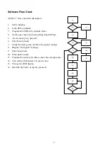
Page 39: ...38 SHEMATIC DIAGRAM Keypad Diagram Chapter 7 ...
Page 40: ...39 Interface Board Schematic ...
Page 41: ...40 ...
Page 42: ...41 ...
Page 43: ...42 ...
Page 44: ...43 ...
Page 45: ...44 ...
Page 46: ...45 POW INV Board Schematic ...
Page 47: ...46 ...


