Chapter 3
51
10.
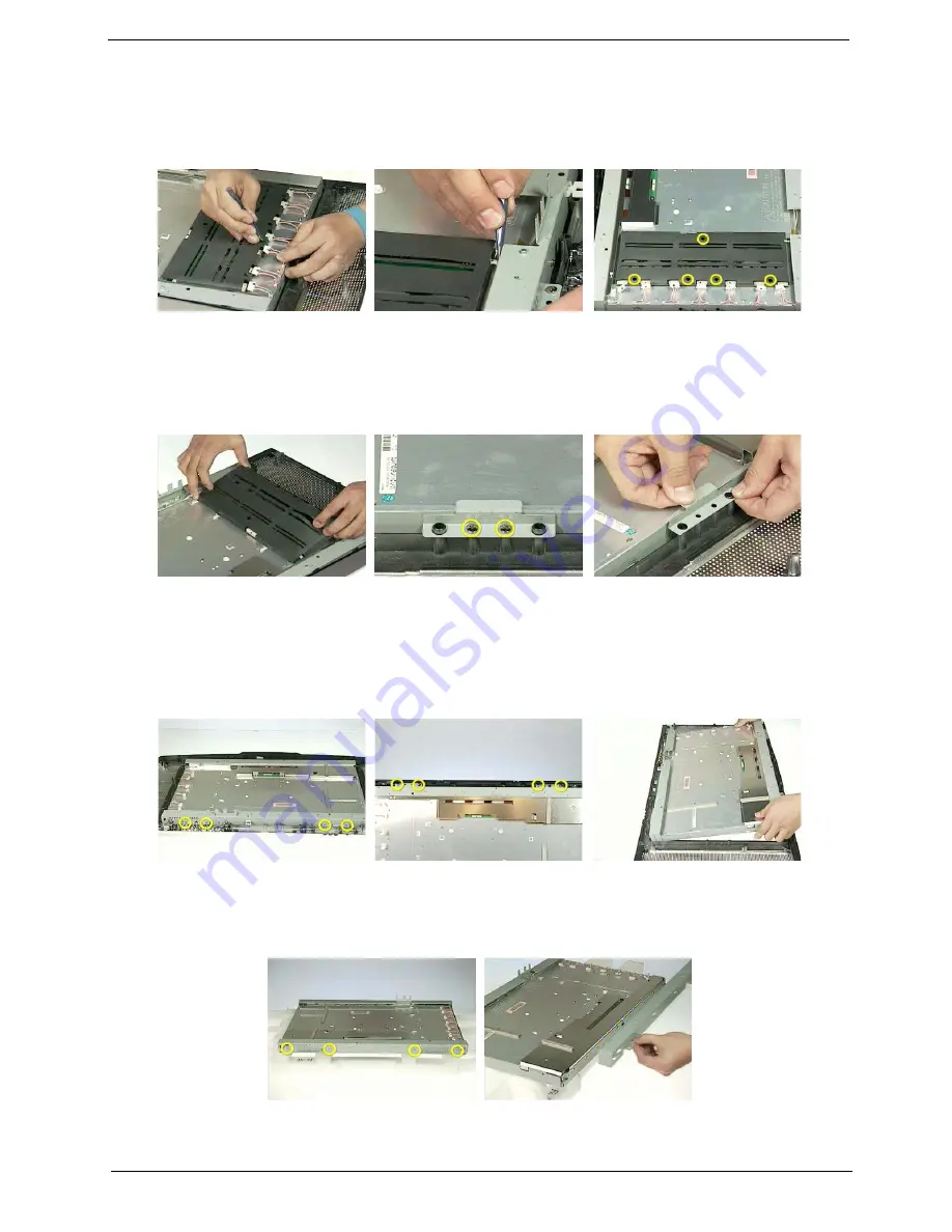
Disconnect the inverter board cable one by one.
11.
Disconnect the inverter board cable on the another side as shown.
12.
Remove the five screws holding the inverter board.
13.
Then detach the inverter board.
14.
Remove the two screws that secure the LCD left bracket.
15.
Detach the LCD left bracket.
16.
Remove the four screws that secure the LCD lower chassis.
17.
Remove the four screws that secure the LCD upper chassis.
18.
Detach the LCD module from the LCD front cover.
Note: The LCD module is heavy, please hold it with
enough strength.
19.
Remove the four screws that secure the LCD upper chassis.
20.
Detach the LCD upper chassis.
21.
Remove the four screws holding the LCD lower chassis.
Summary of Contents for AL2671W
Page 4: ...4 Chapter 1 LCD Main Board Block Diagram Audio Board Block Diagram ...
Page 5: ...Chapter 1 5 Board Layout Board Layout is not ready as the service guide released ...
Page 26: ...26 Chapter 1 ...
Page 30: ...44 Chapter 3 ...
Page 48: ...66 Chapter 4 ...
Page 50: ...84 Chapter 6 Exploded Diagram Acer ...
Page 56: ...90 Chapter 6 NS SCREW T3 12 P NI 86 M01V7 012 Picture Partname Description Part Number ...
Page 57: ...Chapter 6 91 ...


