background image

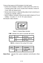
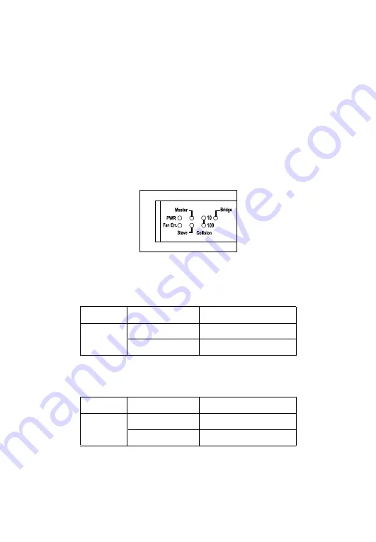
There are three groups of LED indicators in the front panel:

•  System status indicators: Indicate the overall system status of the hub. 

It includes system PWR, Fan Err., Master, Slave indicators, Collision of 

10 and 100M, and Bridge function

•  Network status indicators: Indicate working status of each connection port,

It includes port 100/10M, LNK/ACT

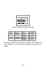
•  Network utilization indicators: Indicate the bandwidth utilization of 10 and

100Mbps. It includes 5, 15, 25, 35, 55+ scales indicators

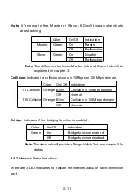
2.4.2 System status indicators

Figure 2-14 System Status Indicators

Master/Slave:  Indicates if the system is stacked to be the Master or Slave

hub.

PWR: Indicates if the system is provided with power.

FAN Err.: Indicates if the cooling FAN is dead.

Color

On/Off

Indication

Green

On

System Powered

Off

No Power

Color

On/Off

Indication

Orange

On

FAN is dead

Off

Normal

2-10

Summary of Contents for ALH-616ds

Page 1: ...Dual Speed Ethernet Hub User s Guide ALH 616ds AcerHub ...

Page 2: ......

Page 3: ......

Page 4: ......

Page 5: ......

Page 6: ...LH 616ds dual speed Hub and it saccessories refer section 1 3 2 Connect the Hub to the external Power supply refer to section 2 4 1 3 Use the normal ports to connect to PCs and computers 4 Use the uplink port to connect to another hub or LAN switch ...

Page 7: ...s II cascading and eliminates the repeater count limitation in IEEE 802 3u specifications It will be easy to construct your own LAN with ALH 616ds by this explicit expanding capability of data transmitting distances and user accounts Installation of AcerHub ALH 616ds is relatively simple and all you have to dois plug the cables from the adapter cards to the ports check the LEDs and you can start n...

Page 8: ... 1 3 Product configuration The product configuration inside the package is shown in the figure 1 1 Please check the contents of the package if there is any missing part beforeusing the hub The accessories of this product include ALH 616ds dual speed hub 1 piece External switching power adapter 1 piece Power cord 1 piece Stacking cable SCSI II 1 piece Stacking kit 1 pairUser s manual 1 piece Figure...

Page 9: ...Figure 2 Aand 2 B Figure 2 A Front Panel Note The ports marked I 2 3 4 5 6 7 8 9 10 11 12 13 14 15 16 are normal ports Please follow the installing procedures to make your network ready 2 1 Connecting to the external power supply Carefully unpack the AcerHub ALH 616ds and it s accessories For the first time that you use this hub please make sure there is nothing missing in the package The procedur...

Page 10: ... 1 Get the hub and power adapter 2 1 2 Place the hub on the desktop and remove the packing box of the power adapter as shown in Figure 2 2 Figure 2 2 Put the hub on desktop and find the proper power adapter 2 2 ...

Page 11: ...the cable and plug the cord into the power jack of the hub as shown in Figure 2 3 AcerSOHO Series Figure 2 3 Connect to the power adapter 2 1 4 Once the hub is connected to the power adapter please connect the power adapter to a power cord as shown in Figure 2 4 Figure 2 4 Connect to the power cord to wall outlet 2 3 ...

Page 12: ...ke it ready 2 2 Installing the hub on your working surface You have to find a solid working surface to place the hub and make sure the equipment is not close to any high voltage power source or over heated sources Also keep away from electronic equipment sensitive to electronic interference The brief procedures of installing your hub should be 2 2 1 Put the hub on a stable working surface as shown...

Page 13: ...ace it above the previous one on the working surface as shown in Figure 2 7 Finally put the stacking kit inthe middle of two sides and click into the stacking hole in the plastic housing Check if all hubs are tightly fastened by the stacking kits and proceed to next step Figure 2 7 Unplug the power and stack two hubs together AcerSOHO Series AcerSOHO Series 2 5 ...

Page 14: ...s with network performance and quality Figure 2 8 Connect hubs by stacking cable 2 2 4 If you are trying to add more hubs in your office you can follow the procedures from 2 2 2 to 2 2 3 repeatedly Be sure not to stack hubs more than 5 include 5 sets in one stack 2 2 5 Plug the power cord into the outlet on wall and check if the power LED lights up The hub is ready for network connection if the po...

Page 15: ...rking by checking if the PWR indicator displays 2 3 2 See if the computer is working and find the RJ 45 connector of the adapter card in computers You can connect UTP Unshielded Twistered Pair cables from normal ports of the hub to computers directly as shown in Figure 2 10 Figure 2 10 Connect to computers 2 7 ...

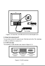
Page 16: ... end of the cable to the RJ 45 connector on the hub as shown in Figure 2 11 Figure 2 11 Connect UTP cable from hub to computers 2 3 4 After connecting to the hub please check if the Link LEDs on the adapter card and the hub named as LNK ACT are lit up as shown in Figure 2 12 If the LED is not lit up there must be something wrong and please reference to chapter 4 for quick trouble shooting 2 8 ...

Page 17: ...ard 2 4 Does the hub work well You can observe the LED status to see if the hub works fine The meanings of LEDs are defined in section 2 4 1 2 4 1 LED overview The locations of LED indicators are shown in Figure 2 13 Figure 2 13 LED overview ACT 2 9 ALH 616ds ...

Page 18: ...es port 100 10M LNK ACT Network utilization indicators Indicate the bandwidth utilization of 10 and 100Mbps It includes 5 15 25 35 55 scales indicators 2 4 2 System status indicators Figure 2 14 System Status Indicators Master Slave Indicates if the system is stacked to be the Master or Slave hub PWR Indicates if the system is provided with power FAN Err Indicates if the cooling FAN is dead Color ...

Page 19: ...occurs in 10Mbps or 100Mbps domain Bridge Indicates if the bridging function is enabled Color On Off Indication Green On Bridge function enabled Off Bridge function disabled Color On Off Indication 10 Collision Orange Blink Collision in 10Mbps domain Off Normal 100 Collision Orange Blink Collision in 100Mbps domain Off Normal Color On Off Indication Master Green On Master Off Malfunction Slave Gre...

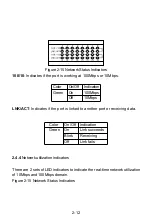
Page 20: ...f 10Mbps LNK ACT Indicates if the port is linked to another port or receiving data Color On Off Indication Green On Link succeeds Blink Receiving Off Link fails 2 4 4 Network utilization indicators There are 2 sets of LED indicators to indicate the real time network utilization of 10Mbps and 100Mbps domain Figure 2 15 Network Status Indicators 2 12 ...

Page 21: ...le 15 of 100M means 15 of 100Mbps 55 of 10M means the utilization is more than 55 of 10Mbps Figure 2 16 Network utilization indicators ROW Speed Color Utilization 10 M 10Mbps Green 5 15 25 Orange 35 55 100 M 100Mbps Green 5 15 25 Orange 35 55 2 13 616ds ...

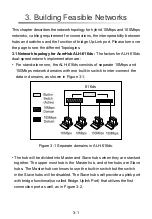
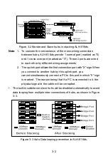
Page 22: ...separate 10Mbps and 100Mbps network domains with one built in switch to inter connect the data in domains as shown in Figure 3 1 3 Building Feasible Networks Figure 3 1 Separate domains in ALH 616ds The hub will be divided into Master and Slave hubs when they are stacked together The upper most hub is the Master hub and other hubs are Slave hubs The Master hub continues to use the built in switch ...

Page 23: ...nk port utilizes the first connection port with X sign When you connect to another hub by this uplink port you cannot simultaneously connect a PC to this port in which II sign is marked The reason being that if a PC is connected to it the physical signal in the cable will be corrupted The built in switches in slave hubs will be disabled automatically to avoid data looping from multiple inter conne...

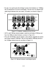
Page 24: ...3 4 Figure 3 4 Unlimited cascading of ALH 616ds All PCs with 10Mbps network adapter cards transmit data at 10Mbps and form the 10Mbps network domain as shown in Figure 3 5 PCs with 10 100Mbps network adapter cards will auto negotiate and switch the network speed to 100Mbps They transmit data at 100Mbps and form the 100Mbps network domain as shown in Figure 3 5 Figure 3 5 Network domains and bridge...

Page 25: ...3 2 1 Connecting to Ethernet Hubs The factors governing hub interconnection are The hubs are only connected by uplink port ALH 616ds will automatically transmit at 10Mbps network speed when connecting to 10Mbps Ethernet hubs and 100Mbps network speed if connected to 100Mbps hubs If multiple ALH 616ds are stacked together users can connect to hubs by the uplink port in slave hubs Therefore other hu...

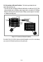
Page 26: ...ALH 616ds will automatically work at 100Mbps network speed when connected to 10 100Mbps Ethernet switching ports and it will work at 10Mbps network speed if connected to 10Mbps switching ports Figure 3 7 Connect to Ethernet Switches No matter if the ALH 616ds hubs are stacked together or not the user always can connect to Ethernet switches by the uplink port 3 5 ...

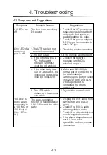
Page 27: ...if the network interface card NIC is installed properly 4 If the other party is a hub or LAN switch the connected ports signal could be cross over 4 Make sure ALH 616ds normal port is connected to the other hub s or switch s uplink port or called cross over port and ALH 616ds uplink port is connected the other s normal port 5 The UTP cable is broken or it is a cross over cable The auto negotiation...

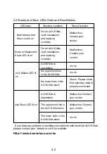
Page 28: ...n the uppermost hub in the ALH 616ds Check Please check if the stacking cable is properly connected it is ok the lower hubs in the ALH 616ds stack ALH 616ds is standalone Malfunction Contact your vendor Malfunction Contact your vendor it is ok The lower hubs in the ALH 616ds stack only Slave LED lit on The uppermost hub in the ALH 616ds stack 4 2 Master and Slave LEDs State and Result Action If yo...

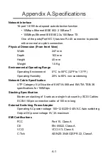
Page 29: ...erating Environment 0 C to 55 C 32 F to 131 F Operating Humidity 20 to 80 non condensing Network Cable Specification UTP Category 5 LAN cable of EIA TIA 568 and EIA TIA TSB 36 specifications for 100Mbps Stacking Specification Maximum stacking of 5 sets as a single hub count by SCSI Cables SCSI II 50 pin connection cable of 100 mm long External Switching Power Adapter Operating AC power voltage 100...

Page 30: ...uct or part has a ninety days warranty or the remainder of the initial warranty period whichever is longer ANI shall not be responsible for any software firmware information or memory data of customer contained in stored on or integrated with any products returned to ANI pursuant to any warranty Before you obtain warranty service you must request an RNA Return Materials Authorization number by cal...

Page 31: ...16 Acer Japan Corporation Tel 81 4 8290 1819 Fax 81 4 8290 1820 Acer Computer B V Tel 31 73 645 9645 Fax 31 73 645 9599 Acer UK Limited Tel 44 1628 533422 Fax 44 1628 524071 http www aceruk co uk Acer Computer France S A R L Tel 33 1 4817 4040 Fax 33 1 4817 4089 Acer Computer GmbH Tel 49 4102 488 0 Fax 49 4102 488 101 Dealers Information Hotline Germany 0180 3234781 End users Information Hotline G...

Page 32: ...100 Recyclable Paper Acer Netxus Inc A Communications Company of Acer P N 49 22013 101 ...

Reviews: