


Appendix B: Acer Altos G5350 rack installation guide
140
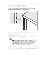
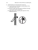
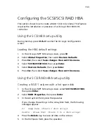
Vertical mounting hole pattern
The four vertical rails of the system rack contain mounting holes
arranged in a manner shown in the figure below:
The system occupies 5U in the rack. Count the U positions and hole
numbers from the bottom up.
The distance from the center of two holes with closer spacing to the
center of the next pair is equivalent to 1U.
Note:
The unit of measurement used in this guide is "U"
(1U = 1.75 inches or 44.45 mm). The total sum of the heights of all
components in the rack measured in "U" cannot exceed the
height of the rack. For more information, refer to the
documentation that came with your system rack.
When installing components, you must start your measurement from
the center of the two holes with closer spacing. Otherwise, the screw
holes on the component may not match those on the rack.
Summary of Contents for Altos G5350
Page 1: ...Acer Altos G5350 Series User s Guide ...
Page 10: ...x ...
Page 11: ...1 System tour ...
Page 31: ...21 5 4 pin power cable connector 6 I2 C bus interface connector No Code Description ...
Page 32: ...1 System tour 22 ...
Page 33: ...2 System setup ...
Page 43: ...3 System upgrade ...
Page 88: ...3 System upgrade 78 ...
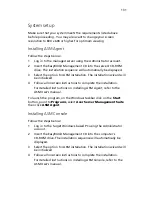
Page 89: ...4 BIOS setup ...
Page 123: ...113 Save Changes Saves changes made in the BIOS setup Parameter Description ...
Page 124: ...4 BIOS setup 114 ...
Page 125: ...5 Troubleshooting ...
Page 136: ...5 Troubleshooting 126 ...
Page 137: ...Appendix A System management utility ...
Page 144: ...Appendix A System management utility 134 ...
Page 145: ...Appendix B Acer Altos G5350 rack installation guide ...
Page 146: ...This appendix shows you how to set up the Altos G5350 server in a rack mount configuration ...
Page 161: ...Appendix C SCSI RAID configuration ...
Page 162: ...This appendix shows you how to create a RAID volume in your SCSI drives ...