


3 System upgrade
48
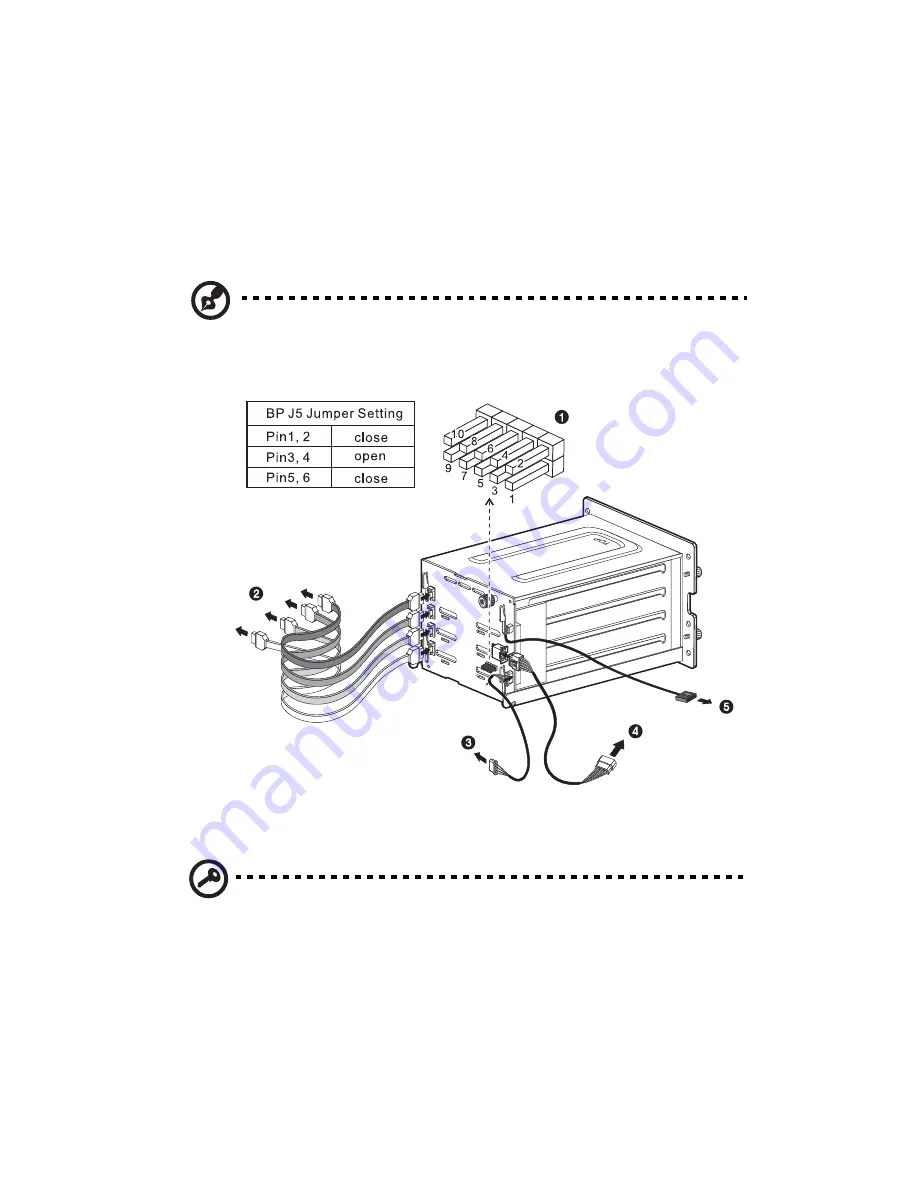
(3) Attach the system’s power cable to the SATA power cable
connector on the backplane
(4)
.
(4) Attach the SATA backplane SAF-TE cable to the JP3 connector
on the backplane
(5)
, then connect the other end of the cable
to the I
2
C connector on the RAID controller.
Refer to the illustration below when installing the SATA
backplane, or removing and replacing the cables.
Note:
The SATA RAID backplane data cables must be installed and
removed in the following order: SATA0, SATA1, SATA2, and
SATA 3.
5
Observe the post-installation instructions described on page 40.
Important:
When you are detaching the hot-plug cage from the
chassis, make sure to first remove all hard disks from their carriers.
For instructions, refer to the succeeding section.
Summary of Contents for Altos G710
Page 1: ...Acer Altos G710 User s Guide ...
Page 10: ...x Setting 183 Index 187 ...
Page 11: ...1 System tour ...
Page 35: ...2 System setup ...
Page 46: ...2 System setup 36 ...
Page 47: ...3 System upgrade ...
Page 69: ...59 2 Pull out the CPU from the socket 2 ...
Page 89: ...4 BIOS setup ...
Page 130: ...4 BIOS setup 120 ...
Page 131: ...5 Troubleshooting ...
Page 142: ...5 Troubleshooting 132 ...
Page 143: ...Appendix A System management ...
Page 151: ...Appendix B Acer Altos G710 rack installation guide ...
Page 152: ...This appendix shows you how to set up the Altos G710 server in a rack mount configuration ...
Page 167: ...Appendix C SCSI RAID configuration ...
Page 168: ...This appendix shows you how to create a RAID volume in your SCSI drives ...
Page 173: ...Appendix D ePanel ...
Page 196: ...Appendix D ePanel 186 ...


