


119
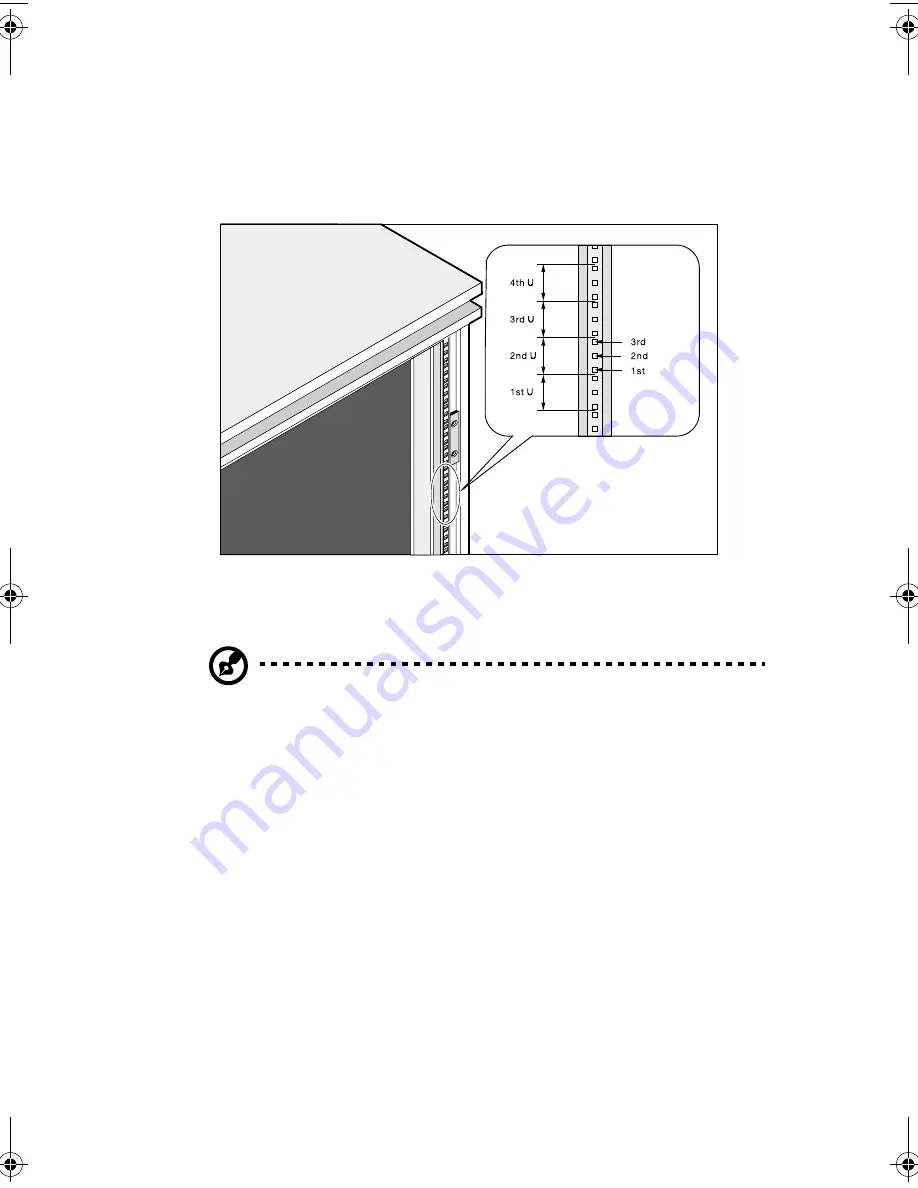
Vertical mounting hole pattern
The four vertical rails of the system rack contain mounting holes
arranged in a manner shown in the figure below:
The system occupies 1U in the rack. Count the U positions and hole
numbers from the bottom up.
Note:
The unit of measurement used in this document is "U" (1U =
1.75 inches or 44.45 mm). The total sum of the heights of all
components in the rack measured in "U" cannot exceed the
height of the rack. For more information, please refer to the
rack’s documentation.
The distance from the center of two holes with closer spacing to the
center of the next pair is equivalent to 1U.
When installing components, you must start your measurement from
the center of the two holes with closer spacing. Otherwise, the screw
holes on the component may not match those on the rack.
aa r500.book Page 119 Thursday, September 20, 2001 11:06 AM
Summary of Contents for Altos R500
Page 1: ...Acer Altos R500 User s guide ...
Page 10: ......
Page 11: ...1 System overview ...
Page 20: ...1 System overview 10 ...
Page 21: ...2 System tour ...
Page 22: ...This chapter discusses the features and components of your computer ...
Page 30: ...2 System tour 20 ...
Page 31: ...3 Setting up your system ...
Page 32: ...This chapter contains step by step instructions on how to set up your system ...
Page 43: ...4 Upgrading your system ...
Page 66: ...4 Upgrading your system 56 ...
Page 67: ...5 Setup utility ...
Page 107: ...Appendix A ASM Pro quick installation guide ...
Page 108: ...This appendix shows you how to set up ASM Pro and its agent software ...
Page 126: ...Appendix A ASM Pro quick installation guide 116 ...
Page 127: ...Appendix B System rack installation guide ...
Page 139: ...129 ...
Page 140: ...Appendix B System rack installation guide 130 ...
Page 142: ...132 ESD 35 post installation 36 preinstallation 35 ...


