


57
9
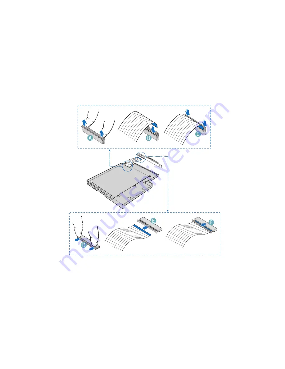
Push down on the connector cover to lock the cable into place. See
letter “C” in the figure below.
10 Open the connector on the interposer board by pulling out on the
connector cover. See letter “D” in the figure below.
11 Insert the loose end of the floppy cable into the interpose board
connector. See letter “E” in the figure below.
12 Push in on the connector cover to lock the cable into place. See
letter “F” in the figure below.
13 Lower the interposer board into the floppy drive tray at the rear of
the floppy drive and engage the notch on the board. See Letter
“A” in the figure below.
14 Attach the interposer board to floppy drive with the screw that
was included with the interposer board. See letter “B” in the
figure below. In the diagram, the flat flex cable been removed for
clarity.
Summary of Contents for Altos R510
Page 1: ...Acer Altos R510 User s Guide ...
Page 12: ......
Page 13: ...1 System information ...
Page 19: ...2 System tour ...
Page 35: ...3 Getting Started ...
Page 36: ...This chapter gives information on setting up and starting to use your system ...
Page 40: ...3 Getting Started 28 ...
Page 41: ...4 Configuring the system ...
Page 104: ...4 Configuring the system 92 ...
Page 105: ...5 BIOS setup ...
Page 154: ...5 BIOS setup 142 ...
Page 155: ...6 Troubleshooting ...
Page 168: ...6 Troubleshooting 156 ...
Page 169: ...Appendix A Management software installation ...
Page 170: ...This appendix shows you how to install the ASM software packages ...
Page 174: ...Appendix A Management software installation 162 ...
Page 175: ...Appendix B Tool less rail kit installation ...
Page 187: ...Appendix C Sensor Table ...
Page 188: ...This appendix shows you the Altos R510 sensor table details ...
Page 191: ...Appendix D SATA RAID Configuration ...
Page 192: ...This appendix shows you how to create SATA RAID ...
Page 196: ...Appendix D SATA RAID Configuration 184 ...
Page 198: ...186 ...


