


4 Configuring the system
58
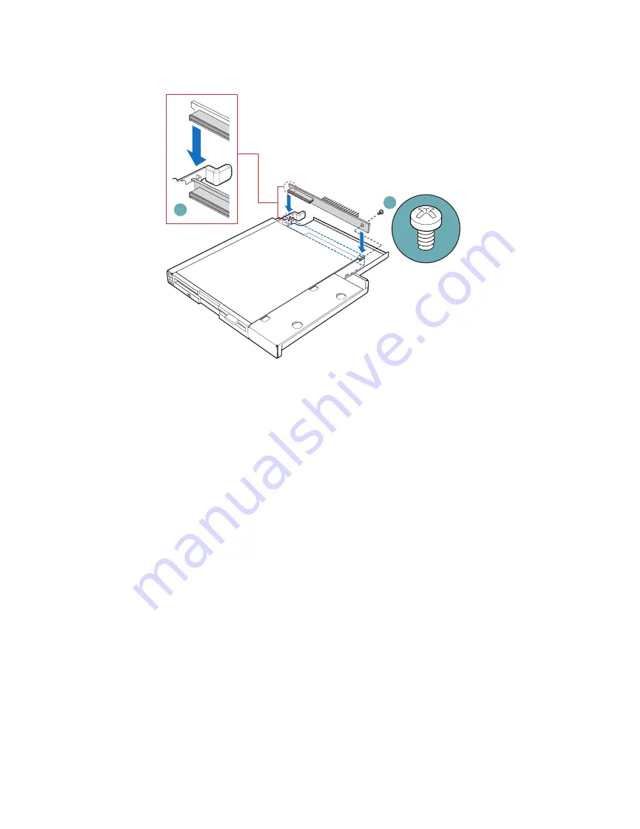
15 Slide the floppy drive assembly into the chassis until it clicks into
place. See letter “A” in the figure below.
16 Connect the 2x2 end of the floppy drive power cable that was
included with your kit to the 2x2 power connector on the SATA
power adapter cable. See letters “B” and “C” in the figure below.
17 Connect the remaining end of the floppy drive power cable to the
power connector on the rear of the floppy drive. See letter “D” in
the figure.
18 Connect the floppy drive data cable that was included with your
kit between the floppy drive data connector and the server board.
See letters “E” and “F” in the figure. See your server board
documentation for assistance in locating the connector location on
the server board.
19 Route the floppy drive data cable over the air baffle, as shown in
the diagram below.
A
B
Summary of Contents for Altos R510
Page 1: ...Acer Altos R510 User s Guide ...
Page 12: ......
Page 13: ...1 System information ...
Page 19: ...2 System tour ...
Page 35: ...3 Getting Started ...
Page 36: ...This chapter gives information on setting up and starting to use your system ...
Page 40: ...3 Getting Started 28 ...
Page 41: ...4 Configuring the system ...
Page 104: ...4 Configuring the system 92 ...
Page 105: ...5 BIOS setup ...
Page 154: ...5 BIOS setup 142 ...
Page 155: ...6 Troubleshooting ...
Page 168: ...6 Troubleshooting 156 ...
Page 169: ...Appendix A Management software installation ...
Page 170: ...This appendix shows you how to install the ASM software packages ...
Page 174: ...Appendix A Management software installation 162 ...
Page 175: ...Appendix B Tool less rail kit installation ...
Page 187: ...Appendix C Sensor Table ...
Page 188: ...This appendix shows you the Altos R510 sensor table details ...
Page 191: ...Appendix D SATA RAID Configuration ...
Page 192: ...This appendix shows you how to create SATA RAID ...
Page 196: ...Appendix D SATA RAID Configuration 184 ...
Page 198: ...186 ...


