


4 Working Inside Your Server
64
3
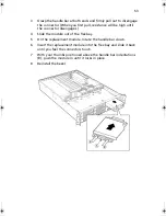
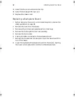
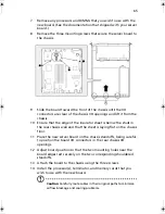
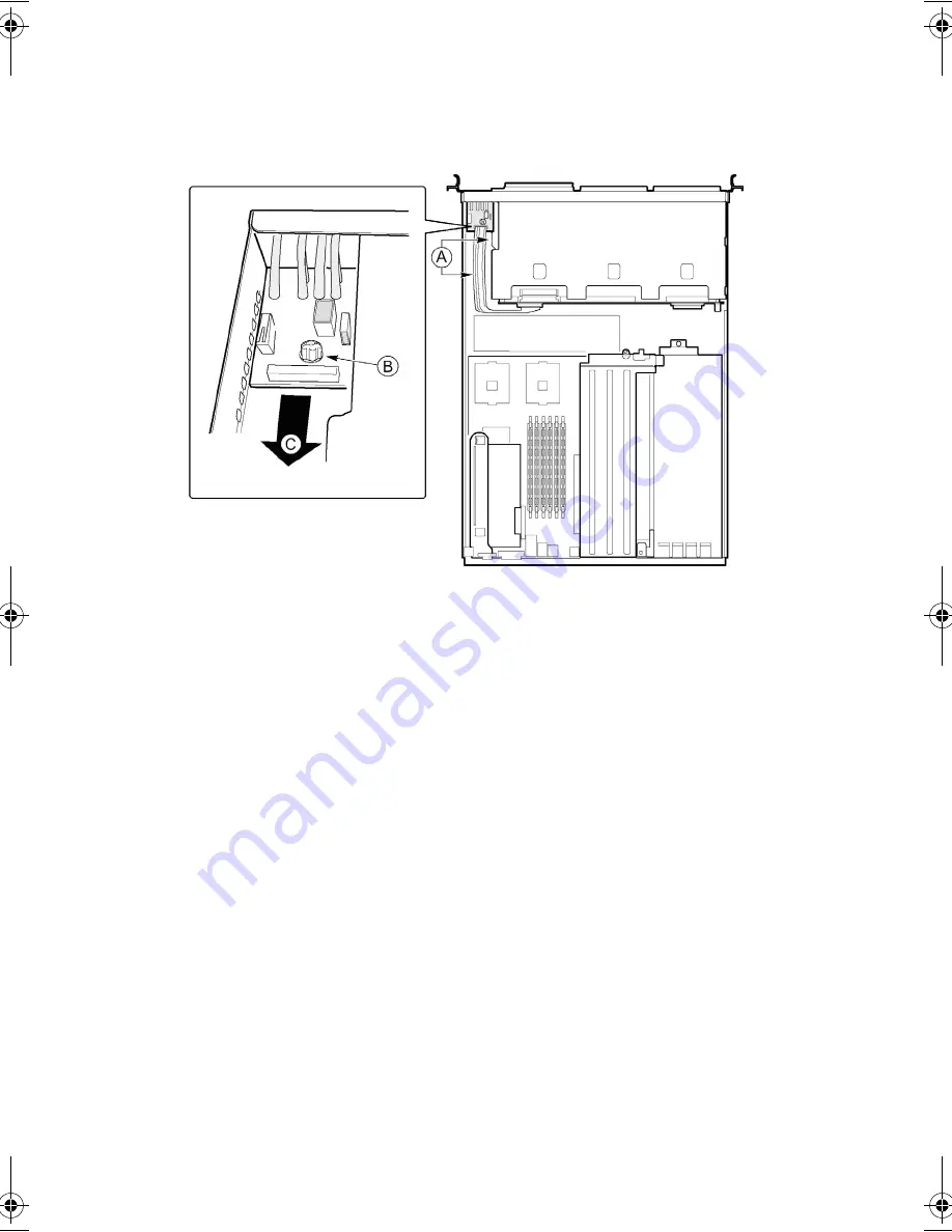
Unplug the USB and backplane cables from the front panel board
(A).
4
Remove the thumbscrew (B) from the board.
5
Remove the front panel board from the chassis (C).
6
Install the new board in the chassis being careful to insert the LED
light pipes into the front panel holes.
7
Secure the board to the chassis with the thumbscrew.
8
Plug the USB and backplane cables back into the front panel
board.
9
Replace the chassis cover.
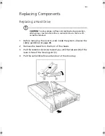
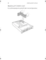
Replacing a Server Board
1
Before removing the cover to work inside the system, observe the
safety guidelines on page 48.
2
Disconnect all cables from the rear I/O of the chassis.
3
Remove the cover from the chassis.
4
Remove the PCI riser cards.
5
Remove the fan module.
6
Unplug all cables connected to the server board.
AR700-e.book Page 64 Tuesday, September 10, 2002 2:31 PM
Summary of Contents for Altos R700 Series
Page 1: ...Altos R700 Chassis Subassembly Product guide...
Page 9: ...1 Chassis Description...
Page 22: ...1 Chassis Description 14...
Page 23: ...2 Assembling the System...
Page 51: ...3 Installing the System in a Rack...
Page 54: ...3 Installing the System in a Rack 46...
Page 55: ...4 Working Inside Your Server...
Page 75: ...Appendix A Equipment Log and Worksheets...
Page 77: ...69 DAT TApe Drive Item Manufacturer Name and Model Name Serial Number Date Installed...


