background image

Altos R700 Series

User’s guide

BS811.f/cppl!!Qbhf!j!!Uvftebz-!Opwfncfs!37-!3113!!21;19!BN

Summary of Contents for Altos R700 Series

Page 1: ...Altos R700 Series User s guide ...

Page 2: ...computer All correspondense concerning your unit should include the serial number model number and purchase information No part of this publication may be reproduced stored in a retrieval system or transmitted in any form or by any means electronic mechanical photocopy recording or otherwise without the prior written permission of Acer Incorporated Model Number _________________________________ Se...

Page 3: ...e at personal expense Class B equipment This device has been tested and found to comply with the limits for a Class B digital device pursuant to Part 15 of the FCC Rules These limits are designed to provide reasonable protection against harmful interference in a residential installation This device generates uses and can radiate radio frequency energy and if not installed and used in accordance wi...

Page 4: ...eption Caution Changes or modifications not expressly approved by the manufacturer could void the user s authority which is granted by the Federal Communications Commission to operate this server Use conditions This part complies with Part 15 of the FCC Rules Operation is subject to the following two conditions 1 this device may not cause harmful interference and 2 this device must accept any inte...

Page 5: ...rking label If you are not sure of the type of power available consult your dealer or local power company 7 Do not allow anything to rest on the power cord Do not locate this product where persons will walk on the cord 8 If an extension cord is used with this product make sure that the total ampere rating of the equipment plugged into the extension cord does not exceed the extension cord ampere ra...

Page 6: ...e indicating a need for service 12 Replace the battery with the same type as the product s battery we recommend Use of another battery may present a risk of fire or explosion Refer battery replacement to a qualified service technician 13 Warning Batteries may explode if not handled properly Do not disassemble or dispose of them in fire Keep them away from children and dispose of used batteries pro...

Page 7: ...ent 18 Baseboard Management Controller 18 Field Replaceable Units and Sensor Data Records 18 System Event Log 19 Platform Event Management 19 Emergency Management Port 20 Acer Advance Server Management ASMe 21 Security 22 Intrusion Switch Monitoring 22 Software Locks 22 Using Passwords 22 Secure Mode 23 Summary of Software Security Features 24 2 Installation Procedures 27 Rearrange the Standoffs 2...

Page 8: ...tility 54 Configuring the Adaptec SCSI Adapter 55 Direct Platform Control DPC Console 57 DPC Console Modes of Operation 57 Running the DPC Console 58 Using the System Setup Utility 59 Creating SSU Diskettes 59 Running the SSU 60 Setting Boot Device Priority 62 Setting Passwords and Security Options 62 Viewing the System Event Log 63 Viewing FRU Information 64 Viewing Sensor Data Records 65 Updatin...

Page 9: ...aracters Are Distorted or Incorrect 90 System Cooling Fans Do Not Rotate Properly 90 Diskette Drive Activity Light Does Not Light 91 CD ROM Drive Activity Light Does Not Light 91 Problems with Application Software 92 Bootable CD ROM Is Not Detected 92 Problems with Network 93 6 Technical Reference 95 Server Board Jumpers 97 Diagnostic LEDs 99 POST Error Codes and Messages 108 BIOS Recovery Beep Co...

Page 10: ...x ...

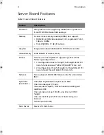
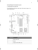
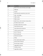
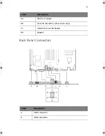
Page 11: ...1 Description ...

Page 12: ...pable of supporting either of the following configurations 1U configuration one full length full height 64 bit PCI riser slot and one Low Profile LP 64 bit PCI riser slot 2U configuration three full length full height 64 bit PCI riser slots and three LP 64 bit PCI riser slots Network Dual on board 10 100 1000 Network Interface Controllers NIC System I O see Table 1 One PS 2 keyboard mouse port 6 p...

Page 13: ...er Board Connector and Component Locations The Altos R700 Server Board comes only in SCSI version Figure 1 is a view of SCSI versions Label Description A System status LED B ID LED C Diagnostic LEDs POST code ...

Page 14: ...X bus C low profile L Secondary processor socket M Secondary processor fan connector N Primary processor socket O Primary processor fan connector P Auxiliary signal connector Q Sys fan 1 connector R Sys fan 2 connector S Main power connector T Battery U Power supply signal connector V ATX front panel connector W SSI front panel connector X Floppy FP IDE connector Y ATA IDE connector Z Floppy drive...

Page 15: ...5 Back Panel Connectors AA USB 2 3 header BB ATA 100 connectors ATA version only CC Hard Disk Drive LED header DD Speaker Label Description A USB 0 connector B Video connector Label Description ...

Page 16: ...annel A connector SCSI server board only D NIC 2 RJ 45 connector E Status LED F Speed LED G NIC 1 RJ 45 connector H Status LED I Speed LED J PS 2 keyboard mouse connector K RJ 45 serial port L USB 1 connector Label Description ...

Page 17: ...7 Processor The Altos R700 server board accommodates one or two Intel Xeon processors with 512k cache in the INT3 FCPGA Socket 604 package This processor uses the 13 micron technology ...

Page 18: ...mory must be installed in pairs starting with bank 1 slots 1B and 1A The controller automatically detects sizes and initializes the memory array depending on the type size and speed of the installed DIMMs and reports memory size and allocation to the server via configuration registers Note Use DIMMs that have been tested for compatibility with the server board Contact your sales representative or ...

Page 19: ...4 bit expansion slot connector Support for either a 1 slot or a 3 slot PCI riser card Support for both full length and low profile PCI cards Riser C provides the following features 184 pin 5 volt keyed 64 bit expansion slot connector Support for either a 1 slot or a 3 slot PCI riser card Support for only low profile PCI cards ...

Page 20: ...DRAM The embedded SVGA video subsystem supports Resolutions up to 1600 x 1200 under 2D and 1024 x 768 under 3D CRT and LCD monitors up to 100 Hz vertical refresh rate The server board supports disabling of the onboard video through the BIOS setup menu or when a plug in video card is installed in any of the PCI slots ...

Page 21: ... the server board with active terminators that cannot be disabled The onboard device must always be at one end of the bus The device at the other end of the cable must also be terminated LVD devices generally do not have termination built in and need to have a termination source provided Non LVDs devices generally are terminated through a jumper or resistor pack on the device itself Note Ultra 320...

Page 22: ...000Base TX compatible PHY IEEE 820 3u auto negotiation support Full duplex support at 10 Mbps 100 Mbps and 1000 Mbps operation Low power 3 3 V device On the Altos R700 Server Board NIC 1 can be used as both a network interface and server management interface NIC Connector and Status LEDs The 82546 controller drives LEDs on the network interface connector that indicate link activity on the LAN and ...

Page 23: ...m fans for cooling the processor s hard drives and add in cards The system fans are mounted in a fan module located in the middle of the chassis to pull cooling air through the chassis The power supply contains a single fan for cooling Note The noise emission is under 70 dB ...

Page 24: ...SU the server may be locked automatically if there is no keyboard or mouse activity for a predefined length of time Once the inactivity lockout timer has expired the keyboard and mouse do not respond until the previously stored password is entered A Y cable can be used if both a PS 2 mouse and keyboard are required at the same time ...

Page 25: ...To accommodate either standard the J5A2 jumper block located directly behind the rear RJ 45 serial port must be jumpered appropriately according to the desired standard Note By default the RJ 45 serial port is configured to support a DSR signal For serial devices that require a DSR signal default the J5A2 jumper must be configured in position 3 4 See figure below B For serial devices that require ...

Page 26: ...ription 16 2 Data Terminal Ready DTR 4 3 Transmitted Data TD 3 4 Signal Ground SGND 5 5 Ring Indicator RI 9 6 Received Data RD 2 7 DCD or DSR DCD DSR 1 or 6 8 Clear to Send CTS 8 RJ 45 Signal Abbreviation DB9 ...

Page 27: ...d supports sleep states s0 s1 s4 and s5 s0 Normal running state s1 Processor sleep state No context will be lost in this state and the processor caches will maintain coherency s4 Hibernate or Save to Disk The memory and machine state are saved to disk Pressing the power button or other wakeup event will restore the system state from the disk and resume normal operation This assumes that no hardwar...

Page 28: ...mergency management port EMP and LAN1 port to send alerts and interact with remote management systems Provides the main front panel control functions power on off reset and so on Field Replaceable Units and Sensor Data Records Field replaceable units FRUs are major modules in the chassis that contain active electronic circuitry FRUs can store information such as board serial number part number nam...

Page 29: ...log SEL where it records significant or critical system events Such events include temperatures and events The BIOS software and other devices can also log events by sending messages to the BMC The SEL is stored in nonvolatile storage You can view the current contents of the SEL by using the System Setup Utility see Viewing the System Event Log on page 63 Platform Event Management Events can trigg...

Page 30: ...onfigure the EMP by using the System Setup Utility SSU or the System Configuration Wizard SCW EMP and Serial Over LAN The RJ 45 Serial 2 port on the back panel can be configured in several different ways as a standard serial port as an Emergency Management Port or for serial output redirection over a LAN You can configure these settings using either the SSU or the SCW Note Important Altos R700 Ser...

Page 31: ...gement when the server is off but still connected to AC power lets you verify the state of the server diagnose hardware problems and power on off or reset the server Run the System Setup Utility to change the server configuration ASMe can use an optional service partition on the server that you are managing The service partition is a special disk partition on the system drive that contains a ROM D...

Page 32: ...cess the system only after you enter the correct password s For example Enable the keyboard lockout timer so that the server requires a password to reactivate the keyboard and mouse after a specified time out period 1 to 120 minutes Set and enable a supervisor password Set and enable a user password Set secure mode to prevent keyboard or mouse input and to prevent use of the front panel reset and ...

Page 33: ...ot is enabled in either the BIOS Setup or SSU May enter either password to exit secure mode Secure Mode Configure and enable the secure boot mode by using the SSU When secure mode is in effect You can boot the server and the operating system will run but you must enter the user password to use the keyboard or mouse You cannot turn off system power or reset the server from the front panel switches ...

Page 34: ... secure mode The server can boot and run the operating system but mouse and keyboard input is not accepted until the user password is entered At boot time if a CD is detected in the CD ROM drive or a diskette in drive A the system prompts for a password When the password is entered the server boots from CD or diskette and disables the secure mode If there is no CD in the CD ROM drive or diskette i...

Page 35: ...ut only the supervisor password will allow Setup to be changed To disable a password change it to a blank entry or press CTRL D in the Change Password menu of the Supervisor Password Option menu found in the Security Subsystem Group To clear the password if you cannot access Setup change the Clear Password jumper see 6 Technical Reference on page 95 Control access to the system other than SSU set ...

Page 36: ...If secure mode is enabled a user password is set then you will be prompted for a password before the server fully boots If secure mode is enabled and the Secure Boot Mode option is also enabled the server will fully boot but will require a password before accepting any keyboard or mouse input Feature Description ...

Page 37: ...2 Installation Procedures ...

Page 38: ...ve board mount standoffs placed as shown you must rearrange them so they match the holes in the server board Failure to properly rearrange the metal standoffs may cause the server board to malfunction and may permanently damage it Your chassis may be different from the illustration ...

Page 39: ...er board 1 While placing the board on the chassis standoffs carefully position the board I O connectors into the rear chassis I O openings 2 Adjust board position to align mounting holes with standoffs 3 Using the screws that came with your chassis mount the board to the chassis Note If you install the server board into an Altos R700 chassis you will not use all of the mounting holes See your chas...

Page 40: ...0 Install the Processor Retention Brackets There are four brackets two for each processor socket For each bracket do the following 1 Place the bracket A on the server board 2 Insert and tighten two screws B to secure the bracket ...

Page 41: ...31 Installing Processors 1 Raise the locking bar on the socket 2 Aligning the pins of the processor with the socket insert the processor into the socket ...

Page 42: ... with your boxed processor for preparing the heat sink and processor for installation 5 Position the heat sink above the processor 6 Aligning the raised metal surfaces place the heat sink on top of the processor 7 Place the heat sink clip 1 so the tab on the clip engages the slot on the heat sink A ...

Page 43: ...33 8 Press one end of the clip down 2 9 Press the other end of the clip down 3 ...

Page 44: ... server board Install from 256 MB to 12 GB of registered ECC memory using up to six DIMMs A 1U chassis requires lowprofile LP 1 2 inch DIMMs DIMMs must be installed in pairs and in the following order 1B and 1A 2B and 2A 3B and 3A Installed DIMMs must be the same speed and must all be registered ...

Page 45: ...hannel A connector SCSI server board only B Internal SCSI channel B connector SCSI server board only C Serial 1 header D Combined Floppy Front Panel IDE connector For use in an Altos chassis only E Fan module connector F Fan module connector G Processor fan connectors For use in a non Altos chassis only H Auxiliary power connector ...

Page 46: ...tware 5 Exit the menu Remove the CD and reboot to install the server operating system After installing the operating system proceed to Acer Advance Server Management Installation Installing your Operating System Install your operating system now Installing Acer Advance Server Management You can install Acer Advance Server Management on a local server or on a remote workstation that is used to mana...

Page 47: ...licable system option 4 Review the Acer Software License Agreement and click Accept 5 If installing to a local server click Install Now If this is a multiple system installation click Add to compile a list of systems and then click Install Now 6 Select Reboot Now or Reboot Later 7 Remove the Acer Advance Server Management CD ...

Page 48: ...2 Installation Procedures 38 ...

Page 49: ...3 Upgrading ...

Page 50: ... Upgrading 40 Tools and Supplies Needed Jumper removal tool or needle nosed pliers Phillips cross head screwdriver 1 bit and 2 bit Pen or pencil Antistatic wrist strap and conductive foam pad recommended ...

Page 51: ...charge ESD ESD protection ESD can damage disk drives boards and other parts We recommend that you perform all procedures in this chapter only at an ESD workstation If one is not available provide some ESD protection by wearing an antistatic wrist strap attached to chassis ground any unpainted metal surface on your server when handling parts ESD and handling boards Always handle boards carefully Th...

Page 52: ...r the wide sides Gripping the wide sides can damage the contacts inside the jumper causing intermittent problems with the function controlled by that jumper Take care to grip with but not squeeze the pliers or other tool you use to remove a jumper or you may bend or break the stake pins on the board ...

Page 53: ...BIOS settings 2 Observe the safety and ESD precautions at the beginning of this chapter 3 Open the chassis and locate the battery 4 Push the upper end of the metal retainer away from the battery the battery pops up 5 Remove the battery from its socket 6 Dispose of the battery according to local ordinance 7 Remove the new lithium battery from its package 8 Being careful to observe the correct polar...

Page 54: ...3 Upgrading 44 ...

Page 55: ...4 Configuration Software and Utilities ...

Page 56: ...4 Configuration Software and Utilities 46 ...

Page 57: ...lly or remotely to assist in system management The service partition uses approximately 40 MB of hard disk space Note It is highly recommended that you install the service partition before installing an operating system For more information see the Service Partition section in the Installation Guide for Acer Advance Server Management This document is included on the ASMe CD shipped with your serve...

Page 58: ...nsole Use to access and monitor the server remotely 57 System Setup Utility SSU and Client System Setup Utility CSSU Use for viewing and configuring server management options viewing the system event log SEL setting boot device priority or setting system security options The SSU can run either from the configuration software CD or from a set of bootable diskettes You can create the diskettes from ...

Page 59: ...ware 76 FRU SDR Load Utility Use to update the Field Replaceable Unit FRU and Sensor Data Record SDR flash components NOTE You must run the FRU SDR Load utility whenever the BMC is updated or if you change your processors 76 Utility Description and brief procedure Page ...

Page 60: ...y combination with the SSU or BIOS Setup Enter the Adaptec SCSI Utility during POST Ctrl A SCSI version only Enter the Promise Technology IDE RAID Utility Ctrl F ATA version only Enter BIOS Setup during POST F2 Abort memory test during POST ESC Press while BIOS is updating memory size on screen Display a menu for selecting the boot device ESC Press anytime after memory check To remove the splash s...

Page 61: ...tup see BIOS Setup OR Press Esc to view POST diagnostic messages and change the boot device priority for this boot only see Temporarily Changing the Boot Device Priority on page 52 3 After pressing F2 or Esc during POST you can press Ctrl A to run the SCSISelect Utility For more information see Running the Adaptec SCSISelect Utility on page 54 4 If you do not press F2 or Esc and do NOT have a devi...

Page 62: ...he problem you might need to clear CMOS memory To clear CMOS either of two methods can be used 1 Press the reset button and hold it down for four seconds or more and then while holding the reset button down press the power button Release both buttons at the same time 2 Move the Clear CMOS jumper found on the configuration jumper block on the baseboard Temporarily Changing the Boot Device Priority ...

Page 63: ...53 4 Press Enter 5 The boot process continues When finished a system prompt displays ...

Page 64: ... Run the Adaptec SCSISelect Utility Use the SCSISelect utility to Change default values Check and or change SCSI device settings that may conflict with those of other devices in the server Do a low level format on SCSI devices installed in the server Running the SCSISelect Utility 1 When this message appears on the video monitor Press Ctrl A for SCSISelect TM Utility 2 Press Ctrl A to run the util...

Page 65: ...adapter in your system Move the cursor to the bus device channel of the one for configuration and press Enter Bus Device Channel 01 06 A 01 06 B F5 Toggle color monochrome Host Adapter Option Comment AIC 7XXX at Bus Device Channel 01 06 A or 01 06 B Configure View Host Adapter Settings Press Enter to view the Configuration Menu SCSI Distk Utilities Press Enter to view the SCSI Disk Utilities Menu ...

Page 66: ...c and make your selection from the following menu Feature Option Comment Exit Utility Yes No When you finish configuring your SCSI devices press Esc Then select Yes and press Enter When this message appears Please press any key to reboot Press any key and the server reboots ...

Page 67: ...DPC Console is independent of the server operating system Even when the server is off you can use DPC Console to verify the state of a server or diagnose a problem with the server hardware DPC console features allows you to Establish connection to remote servers Server Control power on power off and reset operations Retrieve and display entries in the System Event Log SEL Retrieve and display Sens...

Page 68: ...n be Enabled in BIOS Setup If the redirection window does not display information the Console Redirection is either incorrectly configured or disabled the EMP is disabled in BIOS Setup or the server is in protected mode For DPC to function the server must NOT be in graphics mode If the DPC console fails to connect in EMP within 10 seconds and the server can operate in Redirect mode a prompt is dis...

Page 69: ...nfiguration data for these items and the result of making a change to these settings using either utility is identical The SSU consists of a collection of task oriented modules plugged into a common framework called the Application Framework AF The Application Framework provides a launching point for individual tasks and a location for setting customization information Creating SSU Diskettes You c...

Page 70: ...Insert the first SSU diskette in drive A and boot the server from the diskette You are prompted to insert the second diskette After loading completes the SSU starts automatically From the System Resource or ASMe CD ROM Boot the server to the System Resource CD and start the SSU from the Utilities menu From the Service Partition Boot the server to the Service Partition and execute the following DOS...

Page 71: ... so that they take effect the next time you start the SSU There are four user customizable settings Color lets you change the default colors associated with different items on the screen using predefined color combinations The color changes take effect immediately Mode lets you set the desired expertise level novice intermediate or expert The expertise level determines which tasks are visible in t...

Page 72: ...you set or change the administrator password used by both the SSU and the system BIOS This option is not available if both an administrator and a user password are set and you entered only the user password when you started the SSU All changes to the administrator password take effect immediately To change or clear the administrator password 1 From the SSU Main window choose Security 2 Click the A...

Page 73: ...t Key The key combination that can be used to put the server into secure mode Secure Mode Timer If no keyboard or mouse activity occurs during the chosen time interval the server enters secure mode Secure Mode Boot Enable forces the server to boot directly into secure mode Video Blanking Enable turns off the video when the server is in secure mode Floppy Write Enable prevents writing to the disket...

Page 74: ...or event generator ID Viewing FRU Information To view the Field Replaceable Unit FRU information 1 From the SSU Main window choose FRU Manager When you start the FRU Manager it automatically loads the current list of events from nonvolatile memory The FRU Manager window has a navigation pane on the left that displays in a tree format the inventory of components in the server The tree has three cat...

Page 75: ...on an individual SDR displays the information for that SDR in the presentation pane in the upper right The description pane in the lower right displays a description of the currently selected SDR type 2 Use the F4 and F5 keys to scroll the window contents to the left and right to view all of the columns 3 Use the File and SDR menu items to work with the SDR information Open Views data from a previ...

Page 76: ... Update is available only in Expert mode When you start System Update it automatically displays the current revision information for the system firmware and BIOS 3 From the File menu choose Load and choose a uif or hex file to use for the update 4 Click the Update button to perform the update Verifying the Firmware To compare the system firmware in nonvolatile memory with a firmware file 1 Downloa...

Page 77: ...onfiguration To save the system configuration 1 From the SSU Main window choose Config Save Restore Configuration Save Restore is available only in Expert mode 2 Click Save To File and specify a filename and location Restoring a Configuration To restore the system configuration from a file 1 From the SSU Main window choose Config Save Restore Configuration Save Restore is available only in Expert ...

Page 78: ...escape sequence This string is sent to the modem before sending command strings The maximum length for the string is five characters longer strings are truncated Hangup String hang up or drop the connection The EMP automatically sends an ENTER character following this string The maximum length for the string is eight characters longer strings are truncated Modem Dial Command the command to dial a ...

Page 79: ...nts that you want to generate an alert to the Enabled column and move all other events to the disabled column using the following buttons Moves all events from the enabled list to the disabled list Moves the selected event from the enabled list to the disabled list Moves the selected event from the disabled list to enabled the list Moves all events from the disabled list to the enabled list 13 Cli...

Page 80: ... Setup in the previous step fill in the IP addressing boxes Host IP Address the IP address of this server Gateway IP Address the IP address of the router for this server Subnet Mask the IP address for the server s subnet The server uses this to decide if the alert destination is on the same subnet 8 In the Alert IP Address box fill in the IP address of the system you want to receive alerts from th...

Page 81: ...oose Platform Event Manager PEM 2 In the PEM window click Configure LAN and fill in the boxes described in the following steps boxes that aren t listed here are not required for remote access 3 To require a password for remote access enter the password in the Enter New Password box and in the Verify New Password box Passwords can be from 1 to 16 characters long using any ASCII character in the ran...

Page 82: ...cess 1 From the SSU Main window choose Platform Event Manager PEM 2 In the PEM window click Configure EMP and fill in the boxes described in the following steps boxes that aren t listed here are not required for remote access 3 To require a password for remote access enter the password in the Enter New Password box and in the Verify New Password box Passwords can be from 1 to 16 characters long us...

Page 83: ...owed to initiate connections 7 From the Restricted Mode list choose either Enabled a remote system can initiate a connection but cannot perform control operations such as power down reset or front panel NMI Disabled the remote system has full control of the server 8 From the Connection Mode list choose either Direct Connect the serial 2 port on the server is connected by a serial cable to the remo...

Page 84: ...rom the menu to a DOS prompt 3 Insert a diskette into the floppy drive 4 At the DOS prompt for an unformatted diskette type format a s or for a formatted diskette type sys a 5 Press Enter Software Update Package 1 Download the software update 2 Print review and follow the instruction file it supercedes any other instructions Note Be sure to record the current custom BIOS settings They will be clea...

Page 85: ...the access cover and expose the server board For instructions see the product guide accompanying your chassis 3 Move the Recovery Boot RCVRY BOOT jumper from its normal position to the BIOS recovery position see Server Board Jumpers on page 97 4 Reinstall the access cover and connect the power cord 5 Insert the diskette holding the BIOS upgrade and recovery files into drive A 6 Turn on system powe...

Page 86: ...sks for a file name Enter the name of the hex file 7 The program will load the file and then ask if it should upload boot code Press N to continue unless otherwise directed by the release notes or an Acer support professional 8 The program next asks if it should upload operational code Press Y to continue The process of uploading operational code takes a few minutes 9 Once the operational code upd...

Page 87: ...disabled or improperly configured use BIOS Setup to enable it If necessary disable the drive after you are done with the FRU SDR Load Utility How You Use the FRU SDR Load Utility The utility Is compatible with ROM DOS Ver 6 22 MS DOS Ver 6 22 and later versions Windows 95 DOS and Windows 98 DOS Accepts CFG SDR and FRU load files the executable file for the utility is FRU SDR exe Requires the follo...

Page 88: ... device in the server If the given display function fails because of an inability to parse the data present or a hardware failure the utility displays an error message and exits Using Specified CFG File Run the utility with the command line parameter of cfg filename cfg The filename can be any DOS accepted eight character filename string The utility loads the specified CFG file and uses the entrie...

Page 89: ...tility validates the header area of the supplied SDR file it updates the SDR repository area Before programming the utility clears the SDR repository area The utility filters all tagged SDRs depending on the product configuration set in the configuration file Untagged SDRs come automatically programmed The utility also copies all written SDRs to the SDR TMP file it contains an image of what was lo...

Page 90: ...4 Configuration Software and Utilities 80 ...

Page 91: ...5 Solving Problems ...

Page 92: ... this Press Soft boot reset which clears system memory and reloads the operating system Ctrl Alt Del Clear system memory restart POST and reload the operating system Reset button Cold boot reset Turn the system power off and then on This clears system memory restarts POST reloads the operating system and halts power to all peripherals Power off on ...

Page 93: ...conflicts for example two add in boards sharing the same interrupt Are all DIMMs installed correctly Are all peripheral devices installed correctly If the system has a hard disk drive is it properly formatted or configured Are all device drivers properly installed Are the configuration settings made in BIOS Setup correct Is the operating system properly loaded Refer to the operating system documen...

Page 94: ...5 Solving Problems 84 hardware and operating system list on the Acer Customer Support website ...

Page 95: ...not get one unauthorized copies often do not work If you are running the software from a diskette is it a good copy If you are running the software from a CD ROM disk is the disk scratched or dirty If you are running the software from a hard disk drive is the software correctly installed Were all necessary procedures followed and files installed Are the correct device drivers installed Is the soft...

Page 96: ...he hard disk and try running it again Make sure all necessary files are installed If the problems are intermittent there may be a loose cable dirt in the keyboard if keyboard input is incorrect a marginal power supply or other random component failures If you suspect that a transient voltage spike power outage or brownout might have occurred reload the software and try running it again Symptoms of...

Page 97: ...re your video display monitor and keyboard are correctly connected to the system Turn on the video monitor Set its brightness and contrast controls to at least two thirds of their maximum ranges see the documentation supplied with your video display monitor 4 If the operating system normally loads from the hard disk drive make sure there is no diskette in drive A Otherwise place a diskette contain...

Page 98: ... page 91 If a second diskette drive is installed does its activity light turn on briefly If not see Diskette Drive Activity Light Does Not Light on page 91 Confirming Loading of the Operating System Once the system boots up the operating system prompt appears on the screen The prompt varies according to the operating system If the operating system prompt does not appear see Initial System Startup ...

Page 99: ...blem contact your service representative or authorized dealer for help Power Light Does Not Light Check the following Is the system operating normally If so the power LED is probably defective or the cable from the front panel to the server board is loose Are there other problems with the system If so check the items listed under System Cooling Fans Do Not Rotate Properly If all items are correct ...

Page 100: ...ed Contact your service representative or authorized dealer for help Characters Are Distorted or Incorrect Check the following Are the brightness and contrast controls properly adjusted on the video monitor See the manufacturer s documentation Are the video monitor signal and power cables properly installed If the problem persists the video monitor may be faulty or it may be the incorrect type Con...

Page 101: ... relevant switches and jumpers on the diskette drive set correctly Is the diskette drive properly configured Is the diskette drive activity light always on If so the signal cable may be plugged in incorrectly If you are using the onboard diskette controller use the Setup Utility to make sure that Onboard Floppy is set to Enabled If you are using an add in diskette controller make sure that Onboard...

Page 102: ...em is with the copy you are using Make sure all cables are installed correctly Verify that the server board jumpers are set correctly See 6 Technical Reference on page 95 If other software runs correctly on the system contact your vendor about the failing software If the problem persists contact the software vendor s customer service representative for help Bootable CD ROM Is Not Detected Check th...

Page 103: ...ake sure the other adapter supports shared interrupts Also make sure your operating system supports shared interrupts Try reseating the add in adapter The add in adapter stopped working without apparent cause Try reseating the adapter first then try a different slot if necessary The network driver files may be corrupt or deleted Delete and then reinstall the drivers Run the diagnostics Cannot Conn...

Page 104: ...Check with your LAN administrator about the correct networking software that needs to be installed If you are directly connecting two servers no hub you will need a crossover cable see your hub documentation for more information on crossover cables Check the network controller LEDs that are visible through an opening at the system back panel ...

Page 105: ...6 Technical Reference ...

Page 106: ...6 Technical Reference 96 ...

Page 107: ...er a DSR or a DCD signal to the connector See RJ 45 Serial Port on page 15 B CMOS CLR If these pins are jumpered the CMOS settings are cleared These pins should not be jumpered for normal operation C PSWD CLR If these pins are jumpered the password is cleared These pins should not be jumpered for normal operation ...

Page 108: ...pt BIOS recovery These pins should not be jumpered for normal operation E BMC Boot Block Write Enable If these pins are jumpered BMC boot block is erasable and programmable at next reset These pins should not be jumpered for normal operation Label Jumper Name What it does at system reset ...

Page 109: ...e lit resulting in an amber color Likewise if both bits are clear then the red and green LEDs are off During the POST process each light sequence represents a specific Port 80 POST code If a system should hang during POST the Diagnostic LEDs will present the last test executed before the hang When reading the lights the LEDs should be observed from the back of the system The most significant bit M...

Page 110: ...ontroller 0Eh G G G Off Init after Keyboard Test The keyboard controller BAT command result has been verified Next performing any necessary initialization after the keyboard controller BAT command test 0Fh G G G G Write Command Byte 8042 The initialization after the keyboard controller BAT command test is done The keyboard command byte will be written next 10h Off Off Off R Keyboard Init The keybo...

Page 111: ...rt and disabling the MEGAKEY Green PC feature next Making the BIOS code segment writable and performing any necessary configuration before initializing the interrupt vectors 24h Off G R Off Before Vector Configuration is required before interrupt vector initialization has completed Interrupt vector initialization is about to begin 25h Off G R G Init interrupt Vectors Interrupt vector initializatio...

Page 112: ... areas 15h Off G Off A 8254 Timer Test on Channel 2 15h Off G Off A Enable 8042 15h Off G Off A Keyboard Reset 26h Off G A Off Initialize LCD if supported 28h G Off R Off Set Video Mode Initialization before setting the video mode is complete Configuring the monochrome mode and color mode settings next 29h G Off R G Debugger Hook 2Ah G Off A Off Init PCI devices and motherboard devices Pass contro...

Page 113: ...power on message next 37h Off G A A Initialize language module Display splash logo 37h Off G A A Display Sign on message BIOS ID and processor information 38h G Off R R Detect USB Mouse Initializing the bus input and general devices next if present 34h Off G R R Reset IDE Controllers 39h G Off R A Displaying bus initialization error messages 3Ah G Off A R Display Setup Message The new cursor posit...

Page 114: ...eporting 60h Off R R Off Test 8237 DMA Controller The DMA page register test passed Performing the DMA Controller 1 base register test next 65h Off A R G Init 8237 DMA Controller The DMA controller 2 base register test passed Programming DMA controllers 1 and 2 next 7Fh G A A A Extended NMI enable Extended NMI source enabling is in progress 80h R Off Off Off Enable Mouse and Keyboard The keyboard ...

Page 115: ...alization has completed Checking for a locked key next 84h R G Off Off Verify RAM Size Checking for a memory size mismatch with CMOS RAM data next 84h R G Off Off Check ATA Cable Type presence of ATAPI devices 84h R G Off Off Display Keyboard Message 16h Off G G R Display IDE mass storage devices 17h Off G G A Display USB mass storage devices 85h R G Off G Report the first set of POST Errors To Er...

Page 116: ...after the option ROM returned control 9Bh A Off G A Float Processor Initialize Performing any required initialization before the coprocessor test next 9Eh A G G R Enable Interrupts 0 1 2 Checking the extended keyboard keyboard ID and NUM Lock key next Issuing the keyboard ID command next A2h R Off A Off Report second set of POST errors To Error messager 86h R G G Off Prepare And Run Setup Error ma...

Page 117: ...ard controller A7h R G A G Processor initialization before boot A7h R G A G Copy required language strings to shadow RAM Aah A Off A Off Copy required language strings to shadow RAM 000h Off Off Off Off One Beep to indicate end of POST No beep if silent boot is enabled 000h Off Off Off Off POST completed Passing control to INT 19h boot loader next Post Code Diagnostic LED Decoder Description G Gre...

Page 118: ...t Log is full Standard POST Error Messages and Codes Error Code Error Message Pause on Boot 100 Timer Channel 2 Error Yes 101 Master Interrupt Controller Yes 102 Slave Interrupt Controller Yes 103 CMOS Battery Failure Yes 104 CMOS Options not Set Yes 105 CMOS Checksum Failure Yes 106 CMOS Display Error Yes 107 Insert Key Pressed Yes Yes 108 Keyboard Locked Message Yes 109 Keyboard Stuck Key Yes 10...

Page 119: ...e not set Yes 11E Cache memory bad Yes 120 CMOS clear Yes 121 Password clear Yes 140 PCI Error Yes 141 PCI Memory Allocation Error Yes 142 PCI IO Allocation Error Yes 143 PCI IRQ Allocation Error Yes 144 Shadow of PCI ROM Failed Yes 145 PCI ROM not found Yes 146 Insufficient Memory to Shadow PCI ROM Yes Error Code Error Message Pause on Boot 8100 Processor 1 failed BIST No 8101 Processor 2 failed ...

Page 120: ...zation on last boot No 8151 Processor 2 failed initialization on last boot No 8160 Processor 01 unable to apply BIOS update Yes 8161 Processor 02 unable to apply BIOS update Yes 8170 Processor P1 L2 cache Failed Yes 8171 Processor P2 L2 cache Failed Yes 8180 BIOS does not support current stepping for Processor P1 Yes 8181 BIOS does not support current stepping for Processor P2 Yes 8190 Watchdog Ti...

Page 121: ...board Management Controller failed to function Yes 8301 Front Panel Controller failed to Function Yes 8305 Hotswap Controller failed to Function Yes 8420 Intelligent System Monitoring Chassis Opened Yes 84F1 Intelligent System Monitoring Forced Shutdown Yes 84F2 Server Management Interface Failed Yes 84F3 BMC in Update Mode Yes 84F4 Sensor Data Record Empty Yes 84FF System Event Log Full Yes Error...

Page 122: ...ry Beep Codes Beeps Error message POST Progress Code Description 1 Recovery started Start recovery process 2 Recovery boot error Flashing series of POST codes E9h EEh EBh ECh EFh Unable to boot to floppy ATAPI or ATAPI CD ROM Recovery process will retry Series of long low pitched single beeps Recovery failed EEh Unable to process valid BIOS recovery images BIOS already passed control to operating ...

Page 123: ...imer is not operational 5 Processor failure Processor failure detected 6 Keyboard controller Gate A20 failure The keyboard controller may be bad The BIOS cannot switch to protected mode 7 Processor exception interrupt error The CPU generated an exception interrupt 8 Display memory read write error The system video adapter is either missing or its memory is faulty This is not a fatal error 9 ROM ch...

Page 124: ...6 Technical Reference 114 ...

Page 125: ...Appendix A Equipment Log and Power Consumption Worksheets ...

Page 126: ... need some of this information when you run the SSU Item Manufacturer Name and Model Name Serial Number Date Installed System Server Board Primary Processor Speed and Cache Secondary Processor Speed and Cache Video Display Keyboard Mouse Diskette Drive A Diskette Drive B Tape Drive CD ROM Drive Hard Disk Drive 1 Hard Disk Drive 2 Hard Disk Drive 3 Hard Disk Drive 4 ...

Page 127: ...117 Hard Disk Drive 5 Item Manufacturer Name and Model Name Serial Number Date Installed ...

Page 128: ... in Power Usage Worksheet 1 The combined power consumption on 5 V and 3 3 V should not be more then 150W Use the two worksheets in this section to calculate the total used by your configuration For current and voltage requirements of add in boards and peripherals see your vendor documents Worksheet Calculating DC Power Usage 1 List the current for each board and device in the appropriate voltage l...

Page 129: ... 12 V Server Board 6 6 A 0 0 A 2 6 A 1 5 A 5 A 0 0 A Primary Processor Secondary Processor Memory six DIMMs Full Height PCI riser slot see note 1 PCI slot 1 PCI slot 2 PCI slot 3 Low Profile PCI riser slot see note 1 PCI slot 1 PCI slot 2 PCI slot 3 Server Board Current SUBTOTALS System Components see note 2 ...

Page 130: ...otal Combined Power Used by the System 1 From the previous worksheet enter the total current for each column 2 Multiply the voltage by the total current to get the total wattage for each voltage level 3 Add the total wattage for each voltage level to arrive at a total combined power usage on the power supply Total Current Device Current maximum at voltage level 3 3 V 3 3 V Standby 5V 5 V Standby 1...

Page 131: ...e level and total current V X A W Total Watts for each voltage level 3 3 V X ______ A ________ W 5 V X ______ A ________ W 5 V X ______ A ________ W 12 V X ______ A ________ W 12 V X ______ A ________ W Total Combined Wattage ________ W ...

Page 132: ...Appendix A Equipment Log and Power Consumption Worksheets 122 ...

Page 133: ... 35 Creating Bootable Diskette 74 Creating SSU Diskettes 59 Customizing the SSU Interface 61 D Direct Platform Control 57 DPC 57 E Emergency Management Port 20 EMP and Serial Over LAN 20 Exiting the SSU 61 F Field Replaceable Units 18 FRU 18 H Heat sink installation 32 Hot Keys 50 I Initial System Startup 83 ISM 21 ISM Installation 36 K Keyboard and Mouse 14 M Managing the Server Remotely 71 Memor...

Page 134: ...irmware Update Utility 76 Running the SSU 60 S Saving and Restoring the System Configuration 67 SCSI Controller 11 SDR 18 Security 22 Intrusion Switch Monitoring 22 Secure Mode 23 Software Locks 22 Summary of Software Security Features 24 Using Passwords 22 Sensor Data Records 18 Server Board back panel connectors 5 connector and component locations 3 Server Board Installation 29 Server Board Jump...

Page 135: ...g the BIOS 66 Updating the Firmware 66 Upgrading Tools and Supplies Needed 40 V Video 10 Viewing FRU Information 64 Viewing Sensor Data Records 65 Viewing the System Event Log 63 W Working with the SSU Interface 60 ...

Reviews: