
99
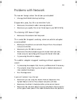
Diagnostic LEDs
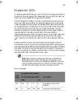
To help diagnose POST failures, a set of four bi-color diagnostic LEDs is
located on the back edge of the baseboard. Each of the four LEDs can
have one of four states: Off, Green, Red, or Amber.
The LED diagnostics feature consists of a hardware decoder and four
dual color LEDs. During POST, the LEDs will display all normal Port80
codes representing the progress of the BIOS POST. Each postcode will
be represented by a combination of colors from the 4 LEDs. The LEDs
are in pairs of green and red. The post codes are broken into two
nibbles, an upper and a lower nibble. Each bit in the upper nibble is
represented by a red LED and each bit in the lower nibble is
represented by a green LED. If both bits are set in the upper and lower
nibble then both red and green LEDs are lit, resulting in an amber
color. Likewise, if both bits are clear then the red and green LEDs are
off.
During the POST process, each light sequence represents a specific
Port-80 POST code. If a system should hang during POST, the Diagnostic
LEDs will present the last test executed before the hang. When reading
the lights, the LEDs should be observed from the back of the system.
The most significant bit (MSB) is the first LED on the left, and the least
significant bit (LSB) is the last LED on the right.
Note
: When comparing a diagnostic LED color string from the
baseboard to those listed in the diagnostic LED decoder in the
following tables, the LEDs on the baseboard should be referenced
when viewed by looking into the system from the back. Reading
the LEDs from left to right, the Hi bit is located on the left.
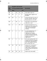
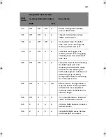
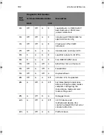
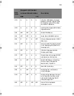
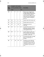
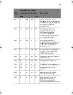
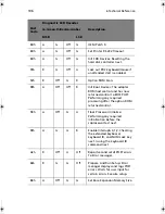
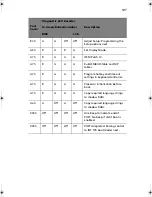
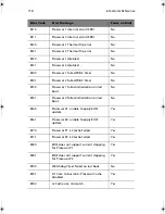
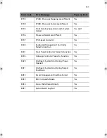
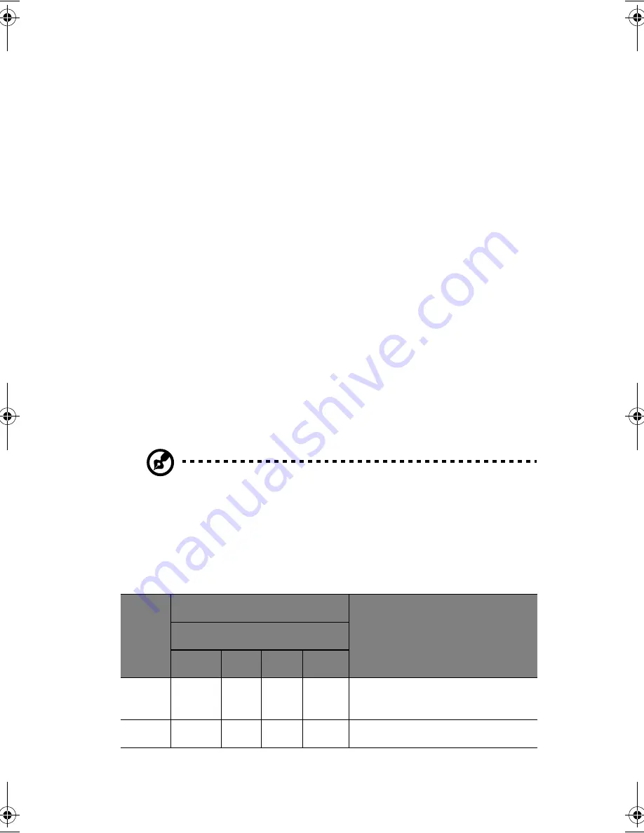
Post Code table:
Post
Code
Diagnostic LED Decoder
Description
G=Green,R=Red,A=Amber
MSB
LSB
07h
Off
G
G
G
Uncompress various BIOS
Modules.
08h
G
Off
Off
Off
Verify password Checksum.
BS811.f/cppl!!Qbhf!::!!Uvftebz-!Opwfncfs!37-!3113!!21;19!BN
Summary of Contents for Altos R700 Series
Page 1: ...Altos R700 Series User s guide ...
Page 10: ...x ...
Page 11: ...1 Description ...
Page 37: ...2 Installation Procedures ...
Page 43: ...33 8 Press one end of the clip down 2 9 Press the other end of the clip down 3 ...
Page 48: ...2 Installation Procedures 38 ...
Page 49: ...3 Upgrading ...
Page 54: ...3 Upgrading 44 ...
Page 55: ...4 Configuration Software and Utilities ...
Page 56: ...4 Configuration Software and Utilities 46 ...
Page 63: ...53 4 Press Enter 5 The boot process continues When finished a system prompt displays ...
Page 90: ...4 Configuration Software and Utilities 80 ...
Page 91: ...5 Solving Problems ...
Page 94: ...5 Solving Problems 84 hardware and operating system list on the Acer Customer Support website ...
Page 105: ...6 Technical Reference ...
Page 106: ...6 Technical Reference 96 ...
Page 124: ...6 Technical Reference 114 ...
Page 125: ...Appendix A Equipment Log and Power Consumption Worksheets ...
Page 127: ...117 Hard Disk Drive 5 Item Manufacturer Name and Model Name Serial Number Date Installed ...
Page 132: ...Appendix A Equipment Log and Power Consumption Worksheets 122 ...


