background image

Acer Altos R700

Service Guide

  PART NO.:  VD.R70VB.001
                                                                                                                                           PRINTED IN TAIWAN

Service guide files and updates are available

on the CSD web; for more information, 

please refer to 

http://csd.acer.com.tw

Summary of Contents for Altos R700 Series

Page 1: ...Acer Altos R700 Service Guide PART NO VD R70VB 001 PRINTED IN TAIWAN Service guide files and updates are available on the CSD web for more information please refer to http csd acer com tw ...

Page 2: ...II Revision History Please refer to the table below for the updates made on Acer Altos R700 service guide Date Chapter Updates ...

Page 3: ...pect to the contents hereof and specifically disclaims any warranties of merchantability or fitness for any particular purpose Any Acer Incorporated software described in this manual is sold or licensed as is Should the programs prove defective following their purchase the buyer and not Acer Incorporated its distributor or its dealer assumes the entire cost of all necessary servicing repair and an...

Page 4: ... bits and pieces of additional information related to the current topic WARNING Alerts you to any damage that might result from doing or not doing specific actions CAUTION Gives precautionary measures to avoid possible hardware or software problems IMPORTANT Reminds you to do specific actions relevant to the accomplishment of procedures ...

Page 5: ... NOT be covered in this generic service guide In such cases please contact your regional offices or the responsible personnel channel to provide you with further technical details 2 Please note WHEN ORDERING FRU PARTS that you should check the most up to date information available on your regional web or channel If for whatever reason a part number change is made it will not be noted in the printe...

Page 6: ...ystem Utilities 20 BIOS Setup Utility 21 Setup Utility Operation 21 Entering the BIOS Setup Utility 22 Entering Setup 25 Main 26 Primary Master and Slave Adapters 27 Processor Settings 28 Advanced Menu 30 Advanced Chipset Control 31 PCI Configuration 32 PCI Device Embedded Devices 33 I O Device Peripheral Configuration 36 Memory Configuration 40 Security 41 Server 43 System Management 45 Serial Co...

Page 7: ...4 BIOS Recovery Beep Codes 75 Bootblock Error Beep Codes 75 Chapter 5 Jumper and Connector Information 78 Jumpers and Connectors 78 System Recovery and Update Jumpers 80 External RJ45 Serial Port Jumper Block 81 Serial Port A 81 Serial Port B 81 Serial Port Multiplexer Logic 81 Rear RJ45 Serial Port 82 Chapter 6 FRU Field Replaceable Unit List 84 Appendix A Model Definition and Configuration 90 Ap...

Page 8: ...bit PCI riser slots and three LP 64 bit PCI riser slots and three LP 64 bit PCI riser slots T Network Dual on board 10 100 1000 Network Interface Controllers NIC T System I O 1 One PS 2 keyboard mouse port 6 pin DIN 2 One VGA video port 15 pin 3 Two external USB ports internal header providing two additional USB 4 One external serial port RJ 45 one internal COM1 header 5 One external SCSI port SCS...

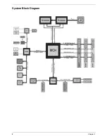
Page 9: ...2 Chapter 1 System Block Diagram ...

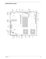
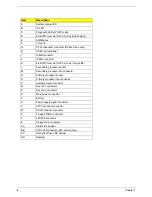
Page 10: ...Chapter 1 3 System Board Layout ...

Page 11: ... low profile L Secondary processor socket M Secondary processor fan connector N Primary processor socket O Primary processor fan connector P Auxiliary signal connector Q Sys fan 1 connector R Sys fan 2 connector S Main power connector T Battery U Power supply signal connector V ATX front panel connector W SSI front panel connector X Floppy FP IDE connector Y ATA IDE connector Z Floppy drive connec...

Page 12: ...nector B Video connector C SCSI channel A connector SCSI server board only D NIC 2 RJ 45 connector E Status LED F Speed LED G NIC 1 RJ 45 connector H Status LED I Speed LED J PS 2 keyboard mouse connector K RJ 45 serial port L USB 1 connector ...

Page 13: ...rd accessory to system F PCI add in card accessory to system G Riser card assembly low profile H Processor air duct I Front panel board J Intrusion switch K Control panel L Flex bay optional DVD CD ROM drive FDD module available M Tape drive bay tape drive available from others N Hard drive bay one of six accessory to system O Backplane board E F G H J I A B C D O N M L K ...

Page 14: ...nel Item Description A Chassis Handles 2 B Drive Bay 1 inch C HDD activity fault Indicator D Flex bay optional DVD CD ROM drive FDD module E Front Panel indicator lights F Tape drive bay tape drive not included A B C D E F ...

Page 15: ...t mounting hole D PCI card bracket full height E AC Power input primary F AC Power input redundant G Power supply module redundant system accessory H Power supply module primary I USB connector 2 J RJ45 serial port K PS 2 mouse keyboard connector L RJ45 NIC 1 connector M SCSI channel A connector If available N Video connector O USB connector1 ...

Page 16: ...DR200 and DDR 266 registered ECC DIMM modules DIMM organization x72 ECC Pin count 184 DIMM capacity 128MB 256MB 512Mb 1GB 2GB DIMMs Serial PD JEDEC Rev 2 0 Voltage options 2 5V VDD VDDQ Interface SSTL2 Two DIMMs must be populated in a bank for a X144 wide memory data path Any or all memory banks may be populated I2C Address Map I2C Bus I2C Add Device PB1 0x58 Heceta5 0x60 SIO PB3 0x30 CPU1 therm s...

Page 17: ...64M x 8 9 1 4 13 2 11 1GB 128M x 72 256 megabit 64M x 4 32 2 4 13 2 11 1GB 128M x 72 512 megabit 64M x 8 18 2 4 13 2 1GB 128M x 72 512 megabit 128M x 4 18 1 4 13 2 12 2GB 256M x 72 512 megabit 128M x4 36 2 4 13 2 12 PCI Riser Slots Item Features Riser B 184 pin 5 volt keyed 64 bit expansion slot connector Support for either a 1 slot or a 3 slot PCI riser card Support for both full length and low p...

Page 18: ...c SCSI transfers SCSI Connectors Pin out J7B1 J7A1 Connector Contact No Signal Name Signal Name Connector Contact No 1 DB 12 DB 12 35 2 DB 13 DB 13 36 3 DB 14 DB 14 37 4 DB 15 DB 15 38 5 DB P1 DB P1 39 6 DB 0 DB 0 40 7 DB 1 DB 1 41 8 DB 2 DB 2 42 9 DB 3 DB 3 43 10 DB 4 DB 4 44 11 DB 5 DB 5 45 12 DB 6 DB 6 46 13 DB 7 DB 7 47 14 DB P DB P 48 15 GROUND GROUND 49 16 GROUND GROUND 50 17 RESERVED RESERV...

Page 19: ...e PHY IEEE 820 3u atuo negotiation support Full duplex support at 10Mbps 100Mbps and 1000Mbps operation Low power 3 3V device ACPI Sleep states Item Description s0 Normal running state s1 Processor sleep state No context will be lost in this state and the processor caches will maintain coherency s4 Hibernate or Save to Disk The memory and machine state are saved to disk Pressing the power button o...

Page 20: ...t from SIO device user configurable IRQ5 IRQ6 Floppy disk IRQ7 IRQ8_L Active low RTC interrupt IRQ9 IRQ10 IRQ11 IRQ12 Mouse interrupt IRQ14 Compatibility IDE interrupt from primary channel IDE devices 0 and1 IRQ15 SMI System Management Interrupt General purpose indicator sourced by the ICH3 S and BMC to the processors SCI System Management Interrupt Used by system to change sleep states and other ...

Page 21: ...BA Rackmount in an idle state at typical office ambient temperature 23 degrees C Sound Power 7 0 BA in an idle state at typical office ambient temperature 23 2 degrees C Operating Shock No errors with a half sine wave shock of 2G with 11 millisecond duration Package Shock Operational after a 24 inch free fall although cosmetic damage may be present Chassis Weight 40 80 Ibs ESD 15KV per Intel Envir...

Page 22: ...SB 3 2 x Gibabit Ethernet ports RJ45 4 1 x RJ 45 for serial support through RJ 45 to serial cable 5 2 x VGA video ports 6 1 x SCSI connector Slots 6 x 64bit PCI X slots Main board SE7500WV2 Drive bays 1 1 x slime type 1 44MB FDD 2 1 x high speed slime type CD ROM or DVD ROM Switching power supply 500W hot swap redundant power supplies Form Factor 2U Rack Mount Weight 23Kg ...

Page 23: ...ion fan status or redundant power supply status This feature is designed primarily for server supervisors and management information system MIS personnel to help them detect errors or potential trouble spots in their network servers through a single management station ASM Pro consists of two major parts T ASM Console a Windows based monitoring station that communicates with the ASM Agents T ASM Ag...

Page 24: ...n NOS Network Operation System is not available There are two cases that NOS is not available POST Power On Self Test and NOS crashes When POST RDM can provide a console redirection feature for remote administrator And if the NOS hangs up ROM can automatically reboot the server or allow the administrator to control the server from remote station This RDM capability bridges the distance barrier in ...

Page 25: ...s Management Bus and Baseboard Management Controller Detailed description of each element is listed below Intelligent Platform Management Interface IPMI IPMI is the specification for the management controller command sets including command sets for sensors event logs and sensor data record access as well as the specification for the data formats including sensor data records event log entries and ...

Page 26: ...Chapter 1 19 ...

Page 27: ...ssages the battery may be bad In this case the system cannot retain configuration values in CMOS Ask a qualified technician for assistance Before you run Setup make sure that you have saved all open files The system reboots immediately after you exit Setup As you change your BIOS Setup examine the system configuration values When you are satisfied that all the values are correct write them down St...

Page 28: ...IOS setup utility as described in this section may be different from those observed on any one pre production version if the system BIOS Setup Utility Operation The ROM resident BIOS Setup utility is only used to configure on board devices The System Setup Utility is required to configure added PCI cards The BIOS Setup utility screen is divided into four functional areas The following table will d...

Page 29: ... the F2 function key to enter Setup as follows Press F2 to enter Setup A few seconds might pass before Setup is entered This is the result of POST completing test and initialization functions that must be completed before Setup can be entered When Setup is entered the Main Menu options page is displayed ...

Page 30: ... is pressed setup is exited and the BIOS continues with POST Select Item The up arrow is used to select the previous value in a pick list or the previous options in a menu item s option list The selected item must then be activated by pressing the Enter key Select Item The down arrow is used to select the next value in a menu item s option list or a value field s pick list The selected item must t...

Page 31: ...o where they were before F9 was pressed without affecting any existing field values F10 Save and Exit Pressing F10 causes the following message to appear Setup Confirmation Save configuration changes and exit now Yes No If Yes is selected and the Enter key is pressed all changes are saved and Setup is exited If No is selected and the Enter key is pressed or the ESC key is pressed the user is retur...

Page 32: ...ion Bar is located at the top of the screen It displays the various major menu selections available to the user T Main Menu T Advanced Menu T Security Menu T Server Menu T Boot Menu T Exit Menu These and associated sub menus are described below ...

Page 33: ... YYYY Set the System Date Floppy A Not Installed 1 44 1 25 1 2MB 3 1 2 Selects Diskette Type Hard Disk Pre delay Disabled 3 seconds 6 seconds 9 seconds 12 seconds 15 seconds 21 seconds 30 seconds Allows slower spin up drives to come ready Primary IDE Master Informational Drive size CD ROM or ATAPI Removable Also selects sub menu Primary IDE Slave Information Drive size CD ROM or ATAPI Removable Al...

Page 34: ... serial console redirection sub menu Primary Master and Slave Adapters Sub menu Selections Feature Option Description Type None Auto Auto allows the system to attempt auto detection of the drive type None informs the system to ignore this drive LBA Mode Control Disabled Enabled Disabled by default if no devices are detected otherwise the setting is auto detected This field is informational only Mu...

Page 35: ...alled Processor POST Speed Information Only Displays the measured processor speed Feature Option Description Processor Retest Disabled Enabled If enabled BIOS will clear historical processor status and retest all processors on the next boot Hyper Threading Technology Disable Enabled Controls the states of Hyper Threading Technology in the processors Processor 1 CPUID CPUID Non Installed Disabled R...

Page 36: ... Processor 2 CPUID CPUID Non Installed Disabled Reports CPUID of Processor 2 if present If empty reports Not Installed If disabled by the BMC reports Disabled Processor 2 L2 Cache Size N A Reports L2 Cache Size for Processor 2 Processor Settings Sub menu Feature Option Description ...

Page 37: ...b menu Advanced Chipset Control N A Selects sub menu May not be present if there are no advanced chipset settings under user control Boot time Diagnostic screen Disabled Enabled If enabled the boot diagnostic screen is displayed during POST If disabled the boot logo is displayed during POST Reset Configuration No Yes Select Yes if you want to clear the System Configuration Data during next boot Au...

Page 38: ...g Enable Disable Only controls legacy wake up Wake On LAN PME PCI X B Enable Disable Only controls legacy wake up on PCI X segment B Wake On PME PCI X C Enable Disable Only controls legacy wake up on PCI X segment C Wake On RTC Alarm Enable Disable Only controls legacy wake up ...

Page 39: ...option is only present if a 2U riser card is installed PCI Slot 3B Enabled Disabled Enable option ROM scan of the device in the selected PCI slot This option is only present if a 2U riser card is installed PCI Slot 1C Enabled Disabled Enable option ROM scan of the device in the selected PCI slot PCI Slot 2C Enabled Disabled Enable option ROM scan of the device in the selected PCI slot This option ...

Page 40: ...33 Chapter 2 PCI Device Embedded Devices Feature Option Description USB Function Disabled Enabled If disabled the USB controllers are turned off and the device resources are hidden from the system ...

Page 41: ...led Enabled If disabled embedded NICs are turned off and the device resources are hidden from the system On board NIC 1 ROM Enabled Disabled If enabled initialize NIC1 expansion ROM On board NIC 2 ROM Enabled Disabled If enabled initialize NIC 2 expansion ROM ...

Page 42: ...sabled the embedded SCSI device is turned off and the device resources are hiddend from the system This option is only present in the SCSI SKU On board SCSI ROM Enabled Disabled If enabled initialize embedded SCSI device expansion ROM This option is only present in the SCSI SKU ...

Page 43: ...Chapter 2 36 I O Device Peripheral Configuration Feature Option Description On board Video Enabled Disabled If disabled embedded video is turned off and the device resources are hidden from the system ...

Page 44: ...8h 2F8h 3E8h 2E8h Selects the base I O address for serial port 2 Serial 2 RJ45 IRQ 4 3 Selects the IRQ for serial port 2 Diskette Controller Disabled Enabled If disabled the diskette controller in the Super I O is disabled Legacy USB support Disabled Keyboard only Auto Keyboard and Mouse If disabled legacy USB support is turned off at the end of the BIOS POST Front Panel USB Disabled Enabled If di...

Page 45: ...Chapter 2 38 ...

Page 46: ...39 Chapter 2 ...

Page 47: ...in the bank has failed and the entire bank has been disabled Memory Bank 2 Installed Not Installed Disabled Displays the current status of the memory bank Disabled indicated that a DIMM in the bank has failed and the entire bank has been disabled Memory Bank 3 Installed Not Installed Disabled Displays the current status of the memory bank Disabled indicated that a DIMM in the bank has failed and t...

Page 48: ...assword press ESC key to abort Once set can be disabled by setting to a null string or clear password jumper on board Set User Password Press Enter When the Enter key is pressed the user is prompted for a password press ESC key to abort Once set can be disabled by setting to a null string or clear password jumper on board Password On Boot Disabled Enabled If enabled requires password entry before ...

Page 49: ...he system Cannot be enabled unless at least one password is enabled Video Blanking Disabled Enabled Blank video when Secure mode is activated A password is required to unlock the system This cannot be enabled unless at least one password is enable This option is only present if the system includes an embedded video controller Power Switch Inhibit Disabled Enabled When enabled the power switch is i...

Page 50: ...error SERR is enabled and is routed to NMI FRB 2 Policy Disable BSP Do Not Disable BSP Retry 3 Times Disable FRB2 Timer Controls the policy of the FRB 2 timeout This option determines when the Boot Strap Processor BSP should be disabled if FRB 2 error occur POST Error Pause Enabled Disabled If enabled the system will wait for user intervention on critical POST errors If disabled the system will bo...

Page 51: ...at the end of POST Boot Monitoring Policy Retry 3 times Retry Service Boot Always Reset Configures the system response to the expiration of the OS Watchdog timer If Retry 3 times is selected the system will attempt to boot the OS partition 3 times followed by the Service Partition once If Retry Service Boot is selected the system will attempt to boot the OS partition 3 times followed by the Servic...

Page 52: ...on field only Chassis Part Number N A Information field only Chassis Serial Number N A Information field only BIOS Revision N A Information field only BMC Device ID N A Information field only BMC Firmware Revision N A Information field only BMC Device Revision N A Information field only PIA Revision N A Information field only SDR Revision N A Information field only HSBP Revision N A Information fi...

Page 53: ... Redirection Baud Rate 9600 19 2K 57 6K 115 2K When console redirection is enabled use the baud rate specified When the Emergency Management Port shares the COM port as console redirection the baud rate must be set to 19 2K to match the Emergency Management Port baud rate unless auto baud feature is used BMC IPMI may override this value BIOS Redirection Flow Control No Flow Control CTS RTS XON XOF...

Page 54: ...makes use of Unicode characters and is intended specifically for use by new Microsoft software or other companies that use Unicode PC ANSI is a legacy selection that uses the same character map as previous Intel server console redirection and is intended to support existing software Note that for VT100 you must select English as your language Feature Option Description ...

Page 55: ...Chapter 2 48 ...

Page 56: ...49 Chapter 2 ...

Page 57: ... No Yes When yes is chosen the BIOS will clear the System Event Log on the next boot Event Logging Disabled Enabled Enables disables System Event Logging Critical Event Logging Disabled Enabled Enables disables critical system event logging including PERR SERR ECC memory errors and NMI ...

Page 58: ...display the OEM logo during POST This option is hiddend if the BIOS does not detect a valid logo in the flash area reserved for this purpose Boot Device Priority N A Selects sub menu Hard Disk Drives N A Selects sub menu Removable Devices N A Selects sub menu ATAPI CD ROM Drives N A Selects sub menu ...

Page 59: ...ce 3 ATAPI CD ROM Drive Attempt to boot from an ATAPI CD ROM drive 4 any SCSI CD ROM Drive Attempt to boot from a SCSI CD ROM containing bootable media This entry will appear if there is a controlled by a BIOS Boot Specification compliant SCSI option ROM 5 PXE UNDI Attempt to boot from a network This entry will appear if there is a network device in the system that is controlled by a PXE compliant...

Page 60: ...53 Chapter 2 ...

Page 61: ...ess the plus key to move it to the top of the list or the minus key to move it down Other bootable cards cover all the boot devices that are not reported to the system BIOS through BIOS boot specification mechanism It may or may not be bootable and may not correspond to any device If BIOS boot spec support is set to limited this item covers all drives that are controlled by option ROMs like SCSI d...

Page 62: ...er 2 Removable Devices Feature Option Description Lists Bootable Removable Devices in the System Use keys to place the removable devices in the boot order you want Includes Legacy 1 44MB floppy 120MB floppy etc ...

Page 63: ...r is prompted if any of the setup fields were modified Load Setup Defaults Load default values for all SETUP items Load Custom Defaults Load values of all Setup items from previously saved Custom Defaults Hidden if custom defaults are not valid to prevent Save Custom Defaults Stores Custom Defaults in NVRAM Discard Changes Read previous values of all Setup items from NVRAM ...

Page 64: ...57 Chapter 2 ...

Page 65: ...Chapter 2 58 ...

Page 66: ...tem to Power Off after a timeout occurs Hard Disk OS Boot Timeout Disable 5 minutes 10 minutes 15 minutes 20 minutes This controls the time limit allowed to load the operating system from a Hard Disk Drive This timer MUST BE DISABLED by Platform Instrumentation Software after operating system load The timeout policy is controlled by the OS Boot Timer policy option PXE OS Boot Timeout Disable 5 min...

Page 67: ...you need the following tools T Wrist grounding strap and conductive mat for preventing electrostatic discharge T A screw driver NOTE The screws for the different components vary in size During the disassembly process group the screws with the corresponding components to avoid mismatch when putting back the components Machine Disassembly and Replacement Chapter 3 ...

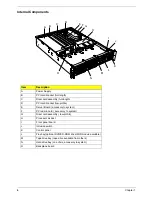
Page 68: ...61 Chapter 3 Disassembly FlowChart ...

Page 69: ... Begin Before proceeding with the disassembly procedure make sure that you do the following 1 Turn off the power to the system and all peripherals 2 Unplug the AC adapter and all power and signal cables from the system 3 Anti static wrist strap ...

Page 70: ...nnected to I O connectors or ports on the back of the chassis T Provide some electrostatic discharge ESD protection by wearing an antistatic wrist strap attached to chassis ground any unpainted metal surface when handling components Removing the Cover 1 Take the front bezel from the chassis 2 While pressing the blue latch button with your left thumb slide the top cover back using the heel of your ...

Page 71: ...rt your finger in the plastic loop On riser card also grasp the opposite end at another side 2 Pull straight up and remove the riser card from the chassis 3 Discard the protective blocks Removing the Air Duct Lift the air duct out of the chassis ...

Page 72: ...ing operation all drive bays must contain either a carrier drive or a carrier with air baffle installed 1 Remove the bezel from the front of the chassis 2 Pull the retention lever toward you until the tab end of the lever is free of the housing slot 3 Pull the carrier drive forward and out of the drive bay ...

Page 73: ...nected to the system turn off the system by pressing the power button and unplug the AC power cord from the system or wall outlet 1 Rotate the handle bar up about 1 4 inch 6 mm to unlatch the module from the bay 2 Grasp the handle bar at both ends and firmly pull out to disengage the connector When you first pull resistance will be high until the connector disengages 3 Slide the module out of the ...

Page 74: ... provides a redundant 1 1 system CAUTION If you do not have the second redundant power supply module you must take the server out of service before replacing the single module 1 Squeeze the module handle to depress the latch that is the right side of the handle 2 Rotate the handle down while pulling the module toward you As you pull the module out support the module with your free hand ...

Page 75: ...that secure the power supply 2 At the end of the power supply remove the screw that attaches the power supply to the standoff in the chassis floor 3 Lift the fan end of the power supply above the chassis standoff and slide it toward the front of the server Lift the power supply out of the chassis ...

Page 76: ...erline push on the tab to release it from the chassis 2 While pushing on the tab lift up on the module to clear the retention stub 3 Slide the module towards the power supply until it comes free 4 Lift the fan module out of the chassis Removing the DIMM Card Press the tab to release the DIMM card ...

Page 77: ...lease both latches from heatsink 2 Then take the heatsink away Removing the CPU Lift up the clip to release the CPU and take it away Removing the Retention Module 1 Remove the 8 screws as shown here to release the retention module 2 Then take both retention modules away ...

Page 78: ... chassis Removing the Front Panel Board 1 Remove the thumbscrew from the board 2 Remove the front panel board from the chassis Removing the MainBoard 1 Remove the three mounting screws that secure the mainboard to the chassis 2 Slide the board toward the front of the chassis until the I O connectors are clear of the chassis I O openings and lift it from the chassis ...

Page 79: ...ter provides troubleshooting information for the Altos R700 T Standard Post Error Messages and Codes T Extended Post Error Messages and Codes T BIOS Recovery Beep Codes T Bootblock Error Beep Codes Troubleshooting Chapter 4 ...

Page 80: ...104 CMOS Options not Set Yes 105 CMOS Checksum Failure Yes 106 CMOS Display Error Yes 107 Insert Key Pressed Yes 108 Keyboard Locked Message Yes 109 Keyboard Stuck Key Yes 10A Keyboard Interface Error Yes 10B System Memory Size Error Yes 10E External Cache Failure Yes 110 Floppy Controller Error Yes 111 Floppy A Error Yes 113 Hard disk 0 Error Yes 114 Hard disk 1 Error Yes 115 Hard disk 2 Error Ye...

Page 81: ... failed on last boot No 8191 4 1 Core to bus ratio Processor Cache disable Yes 8192 L2 Cache size mismatch Yes 8193 CPUID Processor Stepping are different Yes 8194 CPUID Processor Family are different Yes 8195 Front Side Bus Speed mismatch System Halted Yes Halt 8196 Processor Model are different Yes 8197 CPU Speed mismatch Yes 8198 Failed to load processor mirocode Yes 8300 Baseboard Management Y...

Page 82: ...ppy ATAPI or ATAPI CD ROM Recovery process will retry Series of long low pitched single beeps Recovery failed EEh Unable to process valid BIOS recovery images BIOS already passed control to operating system and flash utility 2 long high pitched beeps Recovery complete EFh BIOS recovery succeeded ready for power down reboot Bootblock Error Beep Codes Beeps Error message Description 1 Refresh timer ...

Page 83: ...tected 3 02h Off Off G Off EDO is not supported 3 03h Off Off G G First row memory test failure 3 04h Off G Off Off Mismatched DIMMs in a row 3 05h Off G Off G Base memory test failure 3 06h Off G G Off Failure on decompressing POST module 3 07h 0Dh Off G G G G G G G Off Off Off Off G G G Off Off G G Off Off G Off G Off G Off G Generic memory error 3 0Eh G G G Off SMBUS protocol error 3 0Fh G G G ...

Page 84: ...77 Chapter 4 ...

Page 85: ...Chapter 5 78 Jumpers and Connectors The following figure shows the jumper and connector locations on the system board Jumper and Connector Information Chapter 5 ...

Page 86: ...79 Chapter 5 ...

Page 87: ...red These pins should not be jumpered for normal operation Option Description CMOS Clear If pins 1 and 2 are jumpered default preservation of configuration CMOS through system reset is controlled by the BMC If pins 2 and 3 are jumpered CMOS contents are set to manufacturing default during system reset Password Clear If pins 5 and 6 are jumpered default the current system password is maintained dur...

Page 88: ...nector is located next to the P64 C low profile PCI card slot A standard DH 10 to DB9 cable is available from Acer in the R700 Serial Port Accessory Kit Serial Port B Serial B is an external low profile 8 pin RJ45 connector that is located on the back of the board For those server applications that require an external modem an RJ45 to DB9 adapter is necessary A standard DH 10 to DB9 cable is avail...

Page 89: ...rt configuration standards used by serial port concentrators the J5A2 jumper block located directly behind the rear RJ45 serial port must be jumpered appropriately according to the desired standard NOTE By default as configured in the factory the R700 mainboard will have the rear RJ45 serial port configured to support a DSR signal which is compatible with the Cisco standard For serial concentrator...

Page 90: ...he configuration of the serial device used One of two pin outs configurations are used depending on whether the serial device requires a DSR or DCD signal The final adapter configuration should also match the desired pin out of the RJ45 connector as it can also be configured to support either DSR or DCD For example Modem applications typically use a DCD signal In this case the user would use a DCD...

Page 91: ...ED SERVICE PROVIDERS your Acer office may have a DIFFERENT part number code from those given in the FRU list of this printed Service Guide You MUST use the local FRU list provided by your regional Acer office to order FRU parts for repair and service of customer machines NOTE To scrap or to return the defective parts you should follow the local government ordinance or regulations on how to dispose...

Page 92: ...AR SERIAL PORT SERIAL CABLE ACCESSORY TO ENABLE A SECOND REAR SERIAL PORT FOR INTER SERVER CHASSIS SR2300 CA R7003 001 4 SERIAL CABLE CONVERTER DONGLE CABLE SERIAL CABLE CONVERTER DONGLE CABLES RJ45 TO DB9 FOR SE7500WV2 CA R7003 002 5 TAPE DRIVE CABLE ACCESSORY KIT W I POWER CONNECTOR AND TAPE CABLE TAPE DRIVE CABLE ACCESSORY FOR INTEL SERVER CHASSIS SR2300 TZ R7008 001 6 FRONT BEZEL FRONT BEZEL F...

Page 93: ...HASSIS SR2300 OPTIONAL REDUNDANT 500W POWER SUPPLY MODULE FOR INTEL SERVER CHASSIS SR2300 PY R7007 001 10 SINGLE FAN UPGRADE TO 4 FANS FOR REDUNDANT COOLING MODULE ON CHASSIS SINGLE FAN UPGRADE TO 4 FANS FOR REDUNDANT COOLING FOR INTEL SERVER CHASSIS SR2300 TC R7003 007 11 CPU HEATSINK PLATE HEATSINK FOR AAR700 G900 HI G9004 001 ACER ALTOS R700 CABLE KIT FROMT ITEM 12 TO ITEM 20 12 N A INCLUDE TWO...

Page 94: ...BOVE SAME AS ABOVE 14 BAFFLE DUCT SAME AS ABOVE SAME AS ABOVE 15 FAN BRACKET AND 3 FANS SAME AS ABOVE SAME AS ABOVE 16 FRONT PANEL CABLE SAME AS ABOVE SAME AS ABOVE 17 FLEX CABLE SAME AS ABOVE SAME AS ABOVE Item Picture Part Name Description Part No ...

Page 95: ...OVE 20 RETENTION MODULE AIR DAM AND SCREWS SAME AS ABOVE SAME AS ABOVE ACER ALTOS R700 BOARD KIT FROMT ITEM 21 TO ITEM 23 21 INCLUDE FRONT PANEL BOARD AND LIGHT PIPE ALTOS R700 BOARD KIT TZ R7008 004 22 TWO PCI RISER CARDS SAME AS ABOVE SAME AS ABOVE Item Picture Part Name Description Part No ...

Page 96: ...89 Chapter 6 23 SCSI BACK PLANE SAME AS ABOVE SAME AS ABOVE Item Picture Part Name Description Part No ...

Page 97: ... A 90 The Altos R700 Model No Define 1 Trade Mark 2 Brand Name Acer 3 Description Intel Xeon Processor from 1 8GHz to 2 4GHz or above 4 Product Name Acer Altos R700 Model Definition and Configuration Appendix A ...

Page 98: ...91 Appendix A ...

Page 99: ... and Windows 2000 Advanced Server environment In addition to these tests the network communication functions are also tested under Novell NetWare 6 0 Red Hat Linux 7 3 SCO OpenServer 5 0 6 and SCO Unixware 7 1 1environments Refer to the following lists for components adapter cards and peripherals which have passed these tests Test Compatible Components Appendix B ...

Page 100: ... LSI Enterprise 1600 64bit 66MHz Q12160A i960RN 64 66 Battery Backup Module 64MB SDRAM F W C170 W2K driver 5 25 Acer Altos CD4 0 2ch Ultra160 RAID card PCI LSI MegaRAID Elite 1600 64MB 64bit 66MHz PCI i960RN F W C170 Acer Altos CD 4 0 W2K driver 5 25 LSI MegaRAID Elite 1600 128MB with Battery back up 64bit 66MHz PCI i960RN F W C170 Acer Altos CD 4 0 W2K driver 5 25 0ch Ultra320 SCSI RAID Card Inte...

Page 101: ...el DDS4 20 40GB Internal with Tapeware HP DDS4 20 40GB 68pin interface UW 40MB rev B004 f w C104 C5683 00158 kit includes DDS4 data media clean media acerlogo front bezel and Tapeware v6 20 SP4C AIT 1 35 91GB Internal Sony AIT 1 SDX400C R 5 25 bay Dust proof bezel 35 91GB 68pin UW 40MB f w 0702 Driver 2 00 000 8 for Windows Shipping kit includes AIT1 data media clean media CD with manual drivers a...

Page 102: ... 66 Battery Backup Module 64MB SDRAM F W C170 W2K driver 5 25 Acer Altos CD4 0 2ch Ultra160 RAID card PCI LSI MegaRAID Elite 1600 64MB 64bit 66MHz PCI i960RN F W C170 Acer Altos CD 4 0 W2K driver 5 25 LSI MegaRAID Elite 1600 128MB with Battery back up 64bit 66MHz PCI i960RN F W C170 Acer Altos CD 4 0 W2K driver 5 25 0ch Ultra320 SCSI RAID Card Intel Pionner SQ U320 64Bit 64 66 MHz 80303 64MB DDR S...

Page 103: ...68pin interface UW 40MB rev B004 f w C104 C5683 00158 kit includes DDS4 data media clean media acerlogo front bezel and Tapeware v6 20 SP4C AIT 1 35 91GB Internal Sony AIT 1 SDX400C R 5 25 bay Dust proof bezel 35 91GB 68pin UW 40MB f w 0702 Driver 2 00 000 8 for Windows Shipping kit includes AIT1 data media clean media CD with manual drivers and s w compatibility list AIT 1 data cartridge 35GB Son...

Page 104: ...Enterprise 1600 64bit 66MHz Q12160A i960RN 64 66 Battery Backup Module 64MB SDRAM F W C170 W2K driver 5 25 Acer Altos CD4 0 2ch Ultra160 RAID card PCI LSI MegaRAID Elite 1600 64MB 64bit 66MHz PCI i960RN F W C170 Acer Altos CD 4 0 W2K driver 5 25 LSI MegaRAID Elite 1600 128MB with Battery back up 64bit 66MHz PCI i960RN F W C170 Acer Altos CD 4 0 W2K driver 5 25 0ch Ultra320 SCSI RAID Card Intel Pio...

Page 105: ...el DDS4 20 40GB Internal with Tapeware HP DDS4 20 40GB 68pin interface UW 40MB rev B004 f w C104 C5683 00158 kit includes DDS4 data media clean media acerlogo front bezel and Tapeware v6 20 SP4C AIT 1 35 91GB Internal Sony AIT 1 SDX400C R 5 25 bay Dust proof bezel 35 91GB 68pin UW 40MB f w 0702 Driver 2 00 000 8 for Windows Shipping kit includes AIT1 data media clean media CD with manual drivers a...

Page 106: ...nterprise 1600 64bit 66MHz Q12160A i960RN 64 66 Battery Backup Module 64MB SDRAM F W C170 W2K driver 5 25 Acer Altos CD4 0 2ch Ultra160 RAID card PCI LSI MegaRAID Elite 1600 64MB 64bit 66MHz PCI i960RN F W C170 Acer Altos CD 4 0 W2K driver 5 25 LSI MegaRAID Elite 1600 128MB with Battery back up 64bit 66MHz PCI i960RN F W C170 Acer Altos CD 4 0 W2K driver 5 25 0ch Ultra320 SCSI RAID Card Intel Pion...

Page 107: ...el DDS4 20 40GB Internal with Tapeware HP DDS4 20 40GB 68pin interface UW 40MB rev B004 f w C104 C5683 00158 kit includes DDS4 data media clean media acerlogo front bezel and Tapeware v6 20 SP4C AIT 1 35 91GB Internal Sony AIT 1 SDX400C R 5 25 bay Dust proof bezel 35 91GB 68pin UW 40MB f w 0702 Driver 2 00 000 8 for Windows Shipping kit includes AIT1 data media clean media CD with manual drivers a...

Page 108: ... Enterprise 1600 64bit 66MHz Q12160A i960RN 64 66 Battery Backup Module 64MB SDRAM F W C170 W2K driver 5 25 Acer Altos CD4 0 2ch Ultra160 RAID card PCI LSI MegaRAID Elite 1600 64MB 64bit 66MHz PCI i960RN F W C170 Acer Altos CD 4 0 W2K driver 5 25 LSI MegaRAID Elite 1600 128MB with Battery back up 64bit 66MHz PCI i960RN F W C170 Acer Altos CD 4 0 W2K driver 5 25 0ch Ultra320 SCSI RAID Card Intel Pi...

Page 109: ...el DDS4 20 40GB Internal with Tapeware HP DDS4 20 40GB 68pin interface UW 40MB rev B004 f w C104 C5683 00158 kit includes DDS4 data media clean media acerlogo front bezel and Tapeware v6 20 SP4C AIT 1 35 91GB Internal Sony AIT 1 SDX400C R 5 25 bay Dust proof bezel 35 91GB 68pin UW 40MB f w 0702 Driver 2 00 000 8 for Windows Shipping kit includes AIT1 data media clean media CD with manual drivers a...

Page 110: ...tery Backup Module 64MB SDRAM F W C170 W2K driver 5 25 Acer Altos CD4 0 2ch Ultra160 RAID card PCI LSI MegaRAID Elite 1600 64MB 64bit 66MHz PCI i960RN F W C170 Acer Altos CD 4 0 W2K driver 5 25 LSI MegaRAID Elite 1600 128MB with Battery back up 64bit 66MHz PCI i960RN F W C170 Acer Altos CD 4 0 W2K driver 5 25 0ch Ultra320 SCSI RAID Card Intel Pionner SQ U320 64Bit 64 66 MHz 80303 64MB DDR SCSI Car...

Page 111: ...68pin interface UW 40MB rev B004 f w C104 C5683 00158 kit includes DDS4 data media clean media acerlogo front bezel and Tapeware v6 20 SP4C AIT 1 35 91GB Internal Sony AIT 1 SDX400C R 5 25 bay Dust proof bezel 35 91GB 68pin UW 40MB f w 0702 Driver 2 00 000 8 for Windows Shipping kit includes AIT1 data media clean media CD with manual drivers and s w compatibility list AIT 1 data cartridge 35GB Son...

Page 112: ...tebook Desktop and Server models including T Service guides T User s manuals T Training materials T Bios updates T Software utilities T Spare parts lists T TABs Technical Announcement Bulletin For these purposes we have included an Acrobat File to facilitate the problem free downloading of our technical material Also contained on this website are T Detailed information on Acer s International Trav...

Page 113: ...107 Appendix C ...

Page 114: ...107 Appendix C ...

Reviews: