
4
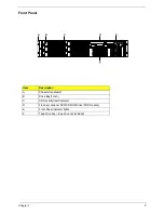
Chapter 1
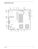
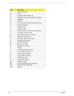
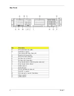
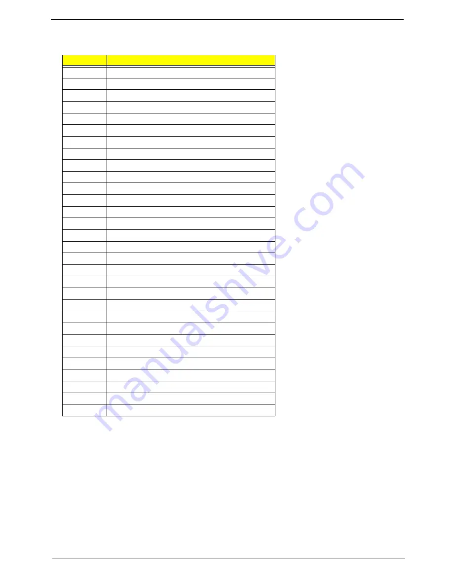
Item
Description
A
System status LED
B
ID LED
C
Diagnostic LEDs( POST code)
D
64-bit PCI riser slot for PCI-X bus B (full height)
E
DIMM slots
F
I/O ports
G
SCSI channel B connector (SCSI version only)
H
COM1 serial header
I
ICMB connector
J
IPMB connector
K
64-bit PCI riser slot for PCI-X bus ( low profile)
L
Secondary processor socket
M
Secondary processor fan connector
N
Primary processor socket
O
Primary processor fan connector
P
Auxiliary signal connector
Q
Sys fan 1 connector
R
Sys fan 2 connector
S
Main power connector
T
Battery
U
Power supply signal connector
V
ATX front panel connector
W
SSI front panel connector
X
Floppy/FP/IDE connector
Y
ATA/IDE connector
Z Floppy
drive
connector
AA
USB 2 & 3 header
BB
ATA-100 connectors (ATA version only)
CC
Hard Disk Drive LED header
DD
Speaker
Summary of Contents for Altos R700 Series
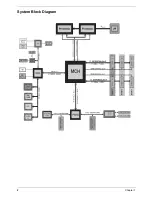
Page 9: ...2 Chapter 1 System Block Diagram ...
Page 10: ...Chapter 1 3 System Board Layout ...
Page 26: ...Chapter 1 19 ...
Page 45: ...Chapter 2 38 ...
Page 46: ...39 Chapter 2 ...
Page 55: ...Chapter 2 48 ...
Page 56: ...49 Chapter 2 ...
Page 60: ...53 Chapter 2 ...
Page 64: ...57 Chapter 2 ...
Page 65: ...Chapter 2 58 ...
Page 68: ...61 Chapter 3 Disassembly FlowChart ...
Page 84: ...77 Chapter 4 ...
Page 86: ...79 Chapter 5 ...
Page 98: ...91 Appendix A ...
Page 113: ...107 Appendix C ...
Page 114: ...107 Appendix C ...


