

8
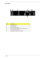
Chapter 1
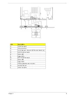
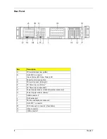
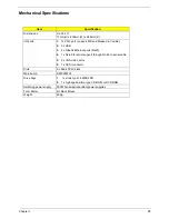
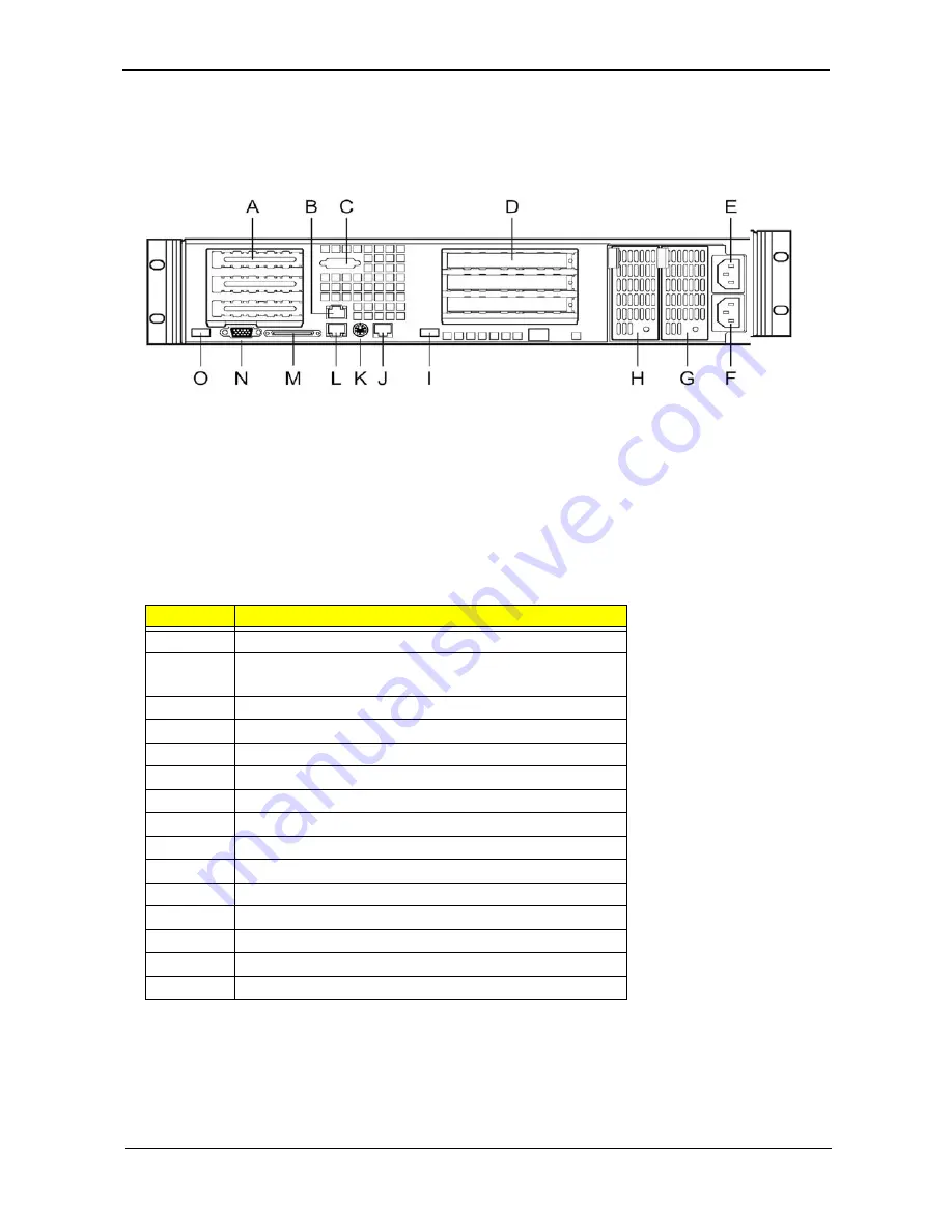
Rear Panel
Item
Description
A
PCI card bracked (low profile)
B
RJ45 NIC 2 connector
Green Status LED/Yellow Status LED
C
Serial A port mounting hole
D
PCI card bracket ( full-height)
E
AC Power input ( primary)*
F
AC Power input (redundant)*
G
Power supply module, redundant (system accessory)*
H
Power supply module, primary*
I
USB connector 2
J
RJ45 serial port
K
PS/2 mouse/keyboard connector
L
RJ45 NIC 1 connector
M
SCSI channel A connector ( If available)
N
Video connector
O
USB connector1
Summary of Contents for Altos R700 Series
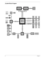
Page 9: ...2 Chapter 1 System Block Diagram ...
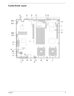
Page 10: ...Chapter 1 3 System Board Layout ...
Page 26: ...Chapter 1 19 ...
Page 45: ...Chapter 2 38 ...
Page 46: ...39 Chapter 2 ...
Page 55: ...Chapter 2 48 ...
Page 56: ...49 Chapter 2 ...
Page 60: ...53 Chapter 2 ...
Page 64: ...57 Chapter 2 ...
Page 65: ...Chapter 2 58 ...
Page 68: ...61 Chapter 3 Disassembly FlowChart ...
Page 84: ...77 Chapter 4 ...
Page 86: ...79 Chapter 5 ...
Page 98: ...91 Appendix A ...
Page 113: ...107 Appendix C ...
Page 114: ...107 Appendix C ...


