
83
Chapter 5
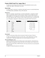
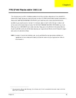
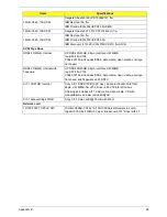
For serial concentrators that require a DSR signal ( Default), the J5A2 jumper block must be configured
as follows: The Serial Port jumper in position 3 and 4. Pin 1 on the jumper is denoted by an arrow directly
next to the jumper block.
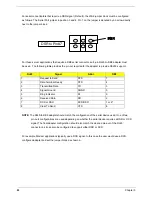
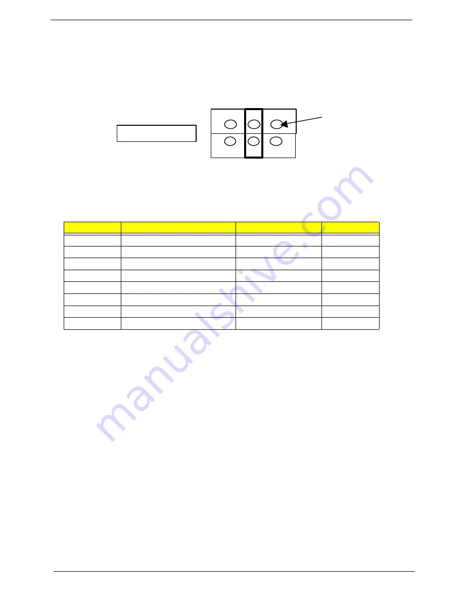
For those server applications that require a DB9 serial connector, an 8-pin RJ45-to-DB9 adapter must
be used. The following table provides the pin-out required for the adapter to provide RS232 support.
NOTE:
The RJ45-to-DB9 adapter should match the configuration of the serial device used. One of two
pin-outs configurations are used depending on whether the serial device requires a DSR or DCD
signal. The final adapter configuration should also match the desired pin-out of the RJ45
connector, as it can also be configured to support either DSR or DCD.
For example, Modem applications typically use a DCD signal. In this case the user would use a DCD-
configured adapter and set the jumper block as shown in.
RJ45
Signal
Abbr
DB9
1
Request to Send
RTS
7
2
Data Terminal Ready
DTR
4
3
Transmitted Data
TD
3
4
Signal Ground
SGND
5
5
Ring Indicator
RI
9
6
Received Data
RD
2
7
DCD or DSR
DCD/DSR
1 or 6*
8
Clear To Send
CTS
8
DSR to Pin#7
PIN 1
Summary of Contents for Altos R700 Series
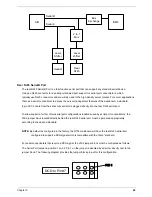
Page 9: ...2 Chapter 1 System Block Diagram ...
Page 10: ...Chapter 1 3 System Board Layout ...
Page 26: ...Chapter 1 19 ...
Page 45: ...Chapter 2 38 ...
Page 46: ...39 Chapter 2 ...
Page 55: ...Chapter 2 48 ...
Page 56: ...49 Chapter 2 ...
Page 60: ...53 Chapter 2 ...
Page 64: ...57 Chapter 2 ...
Page 65: ...Chapter 2 58 ...
Page 68: ...61 Chapter 3 Disassembly FlowChart ...
Page 84: ...77 Chapter 4 ...
Page 86: ...79 Chapter 5 ...
Page 98: ...91 Appendix A ...
Page 113: ...107 Appendix C ...
Page 114: ...107 Appendix C ...


