Getting Started
33
Notes
1 ON = switch to the Right, OFF = switch to the Left.
)
On
Off
*
Mode 2
(not supported
Off
Off
*
Mode 3
(not supported)
11
SOFT SELECT
On
Selects functions using the
hardware switches
12
Not Used
Off
Table 2–5
Ops Panel Switch Functions
Switch Number Function
Recommended Setting
Definition
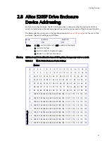
Table 2–6
Mode 0 Drive Addressing
Thumb
Wheel
Switch
Device Slot SEL_ID
Mode 0
1
4 5 6 7 8 9 10 11 12 13 14 15 16 17 18 19
2
20 21 22 23 24 25 26 27 28 29 30 31 32 33 34 35
3
36 37 38 39 40 41 42 43 44 45 46 47 48 49 50 51
4
52 53 54 55 56 57 58 59 60 61 62 63 64 65 66 67
5
68 69 70 71 72 73 74 75 76 77 78 79 80 81 82 83
6
84 85 86 87 88 89 90 91 92 93 94 95 96 97 98 99
7
100 101 102 103 104 105 106 107 108 109 110 111 112 113 114 115
8
100 101 102 103 104 105 106 107 108 109 110 111 112 113 114 115
9
100 101 102 103 104 105 106 107 108 109 110 111 112 113 114 115
10
100 101 102 103 104 105 106 107 108 109 110 111 112 113 114 115
11
100 101 102 103 104 105 106 107 108 109 110 111 112 113 114 115
12
100 101 102 103 104 105 106 107 108 109 110 111 112 113 114 115
13
100 101 102 103 104 105 106 107 108 109 110 111 112 113 114 115
14
100 101 102 103 104 105 106 107 108 109 110 111 112 113 114 115
15
100 101 102 103 104 105 106 107 108 109 110 111 112 113 114 115
Table 2–7
Drive Slot Arrangement: Enclosure Front View
Row/Column
1/#
2/#
3/#
4/#
#/1
Drive 0*
Drive 1
Drive 2
Drive 3
#/2
Drive 4
Drive 5
Drive 6
Drive 7

