Service and Maintenance
5-101
3.
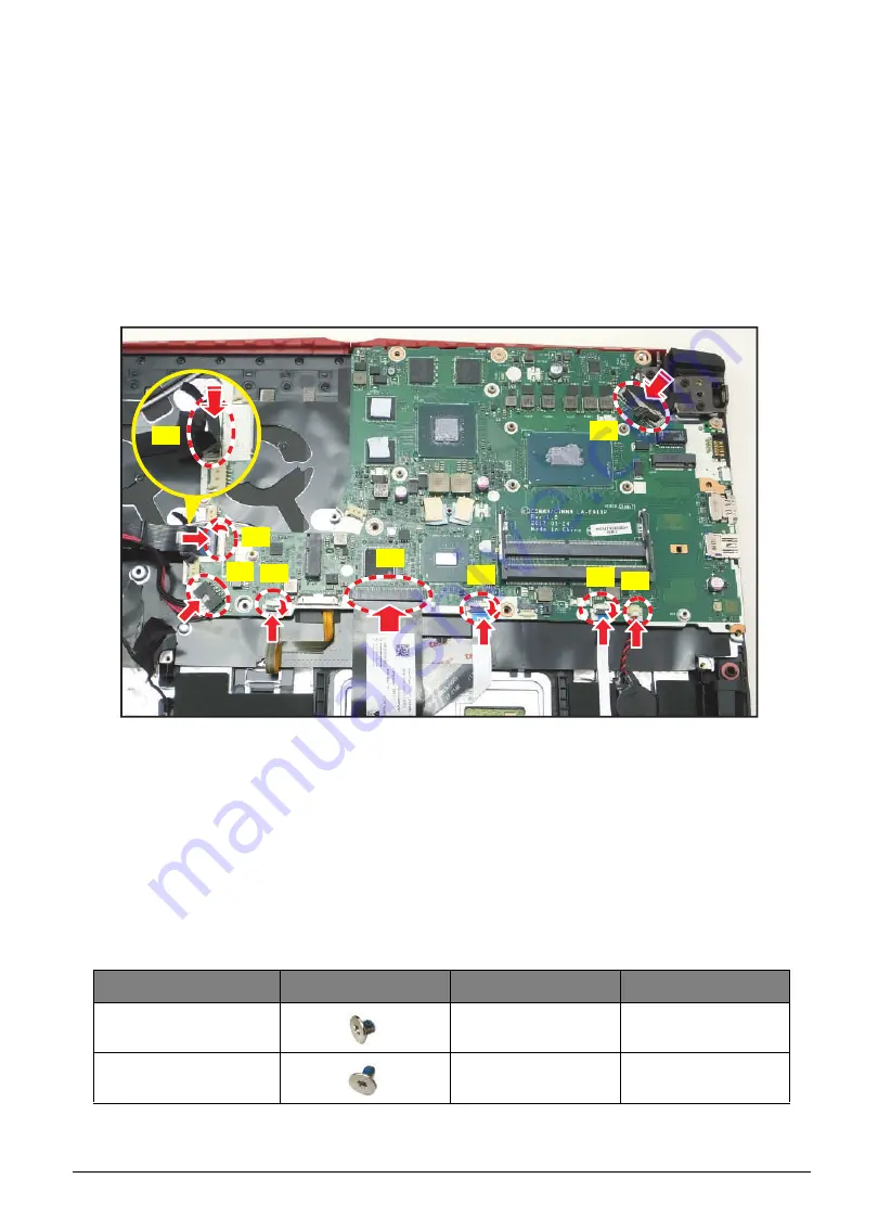
Connect the following cables from the mainboard connectors and secure the latch (if
necessary):
•
HDD cable (A)
•
USB board FFC (B)
•
DC-IN cable (C)
•
Backlight FPC (D)
•
Keyboard FPC (E)
•
Touchpad FFC (F)
•
Hall sensor cable (G)
•
RTC battery cable (H)
•
eDP cable (I)
Figure 5-152. Connecting the Cables
4.
Install the thermal module (see
5.
6.
Install the SSD module (see
).
7.
Install the battery (see
)
Table 5-23. Mainboard Screws
Screw Name
Screw Type
Torque
Quantity
M 2.5 x 3.0
2.0~2.5kgf.cm
2
M 2.0 x 4.0
1.5~2.0kgf.cm
1
C
A
F
D
B
E
G
H
I


