background image

1-3

Hardware Specifications and Configurations

Privacy Control

BIOS user, supervisor, HDD passwords

Kensington lock slot

Storage Subsystem

Hard Disk Drive

320/500GB or larger

2-in-1 card reader, supporting:

Secure Digital™ (SD) Card, MultiMedia Card™ (MMC)

Graphics

Dual independent display support

16.7 million colors

External resolution / refresh rates:

HDMI® port up to 1920 x 1080: 60 Hz

MPEG-2/DVD decoding

WMV9 (VC-1) and H.264 (AVC) decoding

HDMI

®

 (High-Definition Multimedia Interface) with HDCP (High-bandwidth Digital 

Content Protection) support

Audio Subsystem

High-definition audio support

Two built-in stereo speakers

MS-Sound compatible

Built-in microphone
Summary of Contents for AO756

Page 1: ...AO756 V5 171 S E R V I C E G U I D E G U I D E ...

Page 2: ...ity 2 13 WinFlash Utility 2 16 Miscellaneous Tools 2 19 Using DMI Tools 2 19 HDD BIOS Password 2 21 Unlocking the HDD 2 21 Clearing the Password Check and BIOS Password 2 23 Crisis Utility SOP 2 25 When to Use the Crisis SOP 2 25 Creating a USB Flash Crisis Disk 2 25 Using the Crisis Utility Disk 2 28 Chapter 3 Jumper and Connector Locations Mainboard Top View 3 2 Mainboard Bottom View 3 3 LED Boa...

Page 3: ...nstallation 5 16 HDD Board Removal 5 17 HDD Board Installation 5 19 Fan Removal 5 21 Fan Installation 5 23 DIMM Module Removal 5 25 DIMM Module Installation 5 26 WLAN Module Removal 5 27 WLAN Module Installation 5 29 Upper Case Removal 5 31 Upper Case Installation 5 36 Mainboard Removal 5 39 Mainboard Installation 5 41 IO Board Removal 5 43 IO Board Installation 5 45 LED Board Removal 5 47 LED Boa...

Page 4: ...enna Main Installation 5 94 WLAN Antenna Auxiliary Removal 5 96 WLAN Antenna Auxiliary Installation 5 97 Chapter 6 FRU Field Replaceable Unit List Exploded Diagram 6 3 Main Assembly 6 3 Lower Case Assembly 6 5 Upper Case Assembly 6 6 LCD Assembly 6 8 HDD Assembly 6 10 FRU List 6 11 Screw List 6 15 Chapter 7 Test Compatible Components Microsoft Windows 7 Environment Test 7 2 AO756 V5 171 7 2 Chapte...

Page 5: ...de is subject to change without notice Acer Incorporated makes no representations or warranties either expressed or implied with respect to the contents hereof and specifically disclaims any warranties of merchantability or fitness for any particular purpose Any Acer Incorporated software described in this manual is sold or licensed as is Should the programs prove defective following their purchas...

Page 6: ...s command names option letters and words are shown in constant width bold Variables contained within user input are shown in square brackets Example At the prompt type run file name m Keyboard keys are shown in bold italics Example After entering data press Enter Screen output text that represents information displayed on the system such as menus prompts responses to input and error messages are s...

Page 7: ...e guide In such cases contact your regional offices or the responsible personnel channel to provide you with further technical details When ordering FRU parts Check the most up to date information available on your regional web or channel If for whatever reason a part number change is made it may not be noted in this printed service guide For Acer authorized service providers Your Acer office may ...

Page 8: ...tions Hardware Specifications and Configurations 1 2 Features 1 2 Notebook Tour 1 6 Top View 1 6 Front View 1 7 Left View 1 8 Right View 1 9 Base View 1 10 Touchpad Basics 1 11 Keyboard Basics 1 12 System Block Diagram 1 15 Specifications Table 1 16 ...

Page 9: ...1 60GHz 1 70GHz with Turbo Boost up to 1 15GHz 2 40GHz DDR3 1333 MHz 17 W supporting Intel 64 architecture Intel Smart Cache Intel Core i3 2367M i3 2377M i3 3217U Dual Core processor 3 MB L3 cache DDR3 1333 MHz 17 W supporting Intel 64 architecture Intel Smart Cache Intel Pentium 967 987 Dual Core processor 2 MB L3 cache DDR3 1333 MHz 17 W supporting Intel 64 architecture Intel Smart Cache Intel C...

Page 10: ...ard MultiMedia Card MMC Graphics Dual independent display support 16 7 million colors External resolution refresh rates HDMI port up to 1920 x 1080 60 Hz MPEG 2 DVD decoding WMV9 VC 1 and H 264 AVC decoding HDMI High Definition Multimedia Interface with HDCP High bandwidth Digital Content Protection support Audio Subsystem High definition audio support Two built in stereo speakers MS Sound compati...

Page 11: ... Dimension 285 L x 202 W x 20 95 H mm 11 22 x 7 95 x 0 82 inches Weight 1 4 kg 3 09 lbs with 4 cell battery pack Power Adapter and Battery ACPI 2 0 CPU power management standard supports Standby and Hibernation power saving modes Battery 37W 2500mAh 4 cell Li Polymer battery pack Battery life 5 2 hours for V5 171 4 2 hours for AO756 MM07 utility ENERGY STAR Power Adapter 40W 19V AC adapter Voltage...

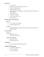
Page 12: ... port D sub 15 pin One Kensington Lock Special Keys and Controls Keyboard 84 85 88 key Fine Tip keyboard International language support Touchpad Multi gesture touchpad supporting four finger scroll pinch rotate accidental cursor jumps page flipping Environment Temperature Operating 0º C to 40º C Non operating 20ºC to 85ºC Humidity non condensing Operating 8 to 90 Non operating 5 to 95 Warranty One...

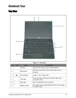
Page 13: ...unications 2 Microphone Receives audio input for sound recording or voice chatting 3 Power Button Press to turn on the system 4 Touchpad Touch sensitive pointing device that functions like a computer mouse 5 Keyboard Use to enter data into the computer 6 Display Screen Also called Liquid Crystal Display LCD screen displays computer output 1 6 5 4 3 2 ...

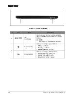
Page 14: ...gital SD and MultiMedia Card MMC for external storage NOTE Only one card can be inserted at a time 2 Power Indicator Indicates the computer power status Off System is off Blue System is on Amber flashing S3 state Battery Indicator Indicates the computer battery status Amber flashing Battery low Amber Battery is charging Blue Battery is fully charged 2 1 MULTIMEDIACARD ...

Page 15: ...nnects to an Ethernet 10 100 1000 based network 2 VGA Port Connects to a VGA cable for external video output 3 Air Vents Use for air flow CAUTION Do not cover the air vents 4 HDMI Port Supports high definition digital video connections 5 USB Ports Connects to USB 2 0 devices AO756 Connects to USB 3 0 devices V5 171 1 2 3 4 5 ...

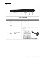
Page 16: ...USB 2 0 devices 3 DC In Jack Connects to an AC adapter 4 Kensington Lock Slot Connects to a Kensington compatible computer security lock NOTE Wrap the computer security lock cable around an immovable object such as a table or handle of a locked drawer Insert the lock into the notch and turn the key to secure the lock Some keyless models are also available 3 1 4 2 ...

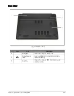
Page 17: ... Figure 1 5 Base View Icon Item Description 1 Battery Bay Houses the computer battery pack 2 Battery Release Latch Insert a suitable tool into the latch and slide to release the battery 3 Base Door Houses the computer HDD main memory and antenna module 3 1 2 ...

Page 18: ... cursor Tapping on the touchpad is the same as clicking the left mouse button 2 Left Button Press the left button to perform selection and execution functions This button is equivalent to the left button on a mouse 3 Right Button Press the right button to perform selection and execution functions This button is equivalent to the right button on a mouse Function Touchpad Left Button Right Button Ex...

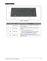
Page 19: ...d in uppercase 2 Fn Function Key Use with other key combinations to perform special functions 3 Windows Key Press to launch the Start menu When used with other keys provides a variety of functions See Windows Key on page 1 13 4 Application Key Press to open the context menu of the current application This key has the same effect as clicking the right mouse button 1 2 3 4 ...

Page 20: ... F Searches for a file or folder D Shows the desktop L Locks the computer if you are connected to a network domain or switch users if you are not connected to a network domain CTRL F Searches for computers if you are on a network CTRL TAB Moves focus from the Start menu to the Quick Launch toolbar and to the system tray Use the right and left arrow keys to move focus to items on the Quick Launch t...

Page 21: ...isplay screen external monitor if connected and both Screen Blank Fn F6 Turns the display screen backlight off to save power Press any key to return Touchpad Toggle Fn F7 Turns the touchpad on and off Speaker Toggle Fn F8 Turns the speaker on or off Num Lock Fn F11 Turns num lock on or off Scroll Lock Fn F12 Turns scroll lock on or off Volume Up Fn Up key Increases audio volume Volume Down Fn Down...

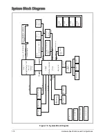
Page 22: ...BANK 0 1 2 3 USB 2 0 conn x1 Option for USB3 0 DC DC Interface CKT Sandy Bridge ULV Power Circuit DC DC 204pin DDRIII SO DIMM X2 Intel 1 5V DDRIII 1066 1333 Memory BUS DDRIII PCH HD Audio Panther Point M ENE KB9012 BGA1023 Intel SPI ROM x2 USBx14 3 3V 48MHz SATA HDD Conn 989pin BGA LAN GbE CardReader Broadcom 57785 CLK 100MHz eDP UMA IO B USB 2 0 conn x2 GEN3 LS 8942P Port 1 100MHz MINI Card WLAN ...

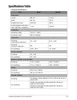
Page 23: ...0ºC 40ºC 32ºF 104ºF Operating writing to optical disc N A N A Non operating 20ºC 85ºC 4º 185ºF Relative humidity Operating 8 90 Non operating 5 95 Maximum altitude unpressurized Operating 15 m 3 048 m 50 ft 10 000 ft Non operating 15 m 12 192 m 50 ft 40 000 ft Shock Operating 60 g 11 ms half sine Non operating 240 g 2 ms half sine Random vibration Operating The adapter shall be subjected to 10 Hz ...

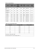
Page 24: ...7785XB0KMLG QFN 68P E LAN CTRL USB 2 0 2 USB2 0 1 USB3 0 Super I O controller N A Bluetooth Wireless Foxconn T77H365 00 Broadcom 43228 20702 Foxconn T77H348 02 WB222 Athors LITE ON Broadcom 43228 20702 LITE ON WCBN611AH AA_WB222 Broadcom WB222 Wireless LITE ON Atheros HB125 HON HAI Broadcom 4313 PCMCIA N A Audio codec Realtek ALC271X VB6 CG Item Specification CPU Intel Sandy Ivy Bridge Dual Core P...

Page 25: ...l Core 967 1 3G dual 5GT s 32nm 2MB BGA1023 0 7 1 2V i5 2467M 1 6G dual 5GT s 32nm 3MB BGA1023 0 7 1 2V i3 2367M 1 4G dual 5GT s 32nm 3MB BGA1023 0 7 1 2V i3 2377M 1 5G dual 5GT s 32nm 3M BGA1023 0 7 1 2V i5 3317U 1 7G dual 5GT s 22nm 3M BGA1023 0 7 1 2V i3 3217U 1 8G dual 5GT s 22nm 3M BGA1023 0 7 1 2V i7 3667U 2 0G dual 5GT s 22nm 3M BGA1023 0 7 1 2V CPU Temp Fan Speed RPM SPL Spec dBA 50 3400 2...

Page 26: ...OFF 91 C OS shut down at 100 C H W shut down at 92 C Item Specification Memory controller Intel Sandy IVY Bridge Processor Memory size N A DIMM socket number x 2 Socket Channel A DIMM 1 Channel B DIMM 2 Supports memory size per socket 1GB 2GB 4GB Supports maximum memory size Total 8GB Supports DIMM type SODIMM Supports DIMM Speed DDR3 1066 1333 Support DIMM voltage 1 5V Supports DIMM package DDR3 ...

Page 27: ... N A Compatibility N A Sampling rate N A Item Specification BIOS vendor MXIC BIOS Version 1 00 BIOS ROM type SPI BIOS ROM size 4MB 1 1MB 1 Features Insyde code base Flash ROM 5 MB Support Acer UI Support multi boot Suspend to RAM S3 Disk S4 Various hot keys for system control Support SMBIOS 2 7 PCI2 3 DMI utility for BIOS serial number configurable Support PXE Support WinFlash Wake on LAN from S3 ...

Page 28: ...tures Supports 10 100 1000BASE T full duplex half duplex MAC Item Specification Type AF1S Total number of keypads 84 US 85 UK 88 JA Windows logo key Yes Internal external keyboard work simultaneously Plug USB keyboard to the USB port directly Yes Features Phantom key auto detect Support independent pgdn pgup keys Support reverse T cursor keys Factory configurable different languages by OEM custome...

Page 29: ...00G Bytes per sector 512Bytes 4096Bytes 4096Bytes 4096Bytes 4096Bytes 4096Bytes Data heads 2 2 Drive Format Disks 1 2 Spindle speed RPM 5400RPM Performance Specifications Buffer size 8MB Interface SATA Fast data transfer rate Mbits sec max 3 0Gbits s 3 0Gbits s Media data transfer rate Mbytes sec max 124 25Mbytes sec 130 5Mbytes s 144 Mbytes sec 147 Mbytes sec 125 5Mbytes sec 144 Mbytes sec DC Pow...

Page 30: ...isplay resolution pixels 1366 x 3 RGB x 768 Pixel Pitch mm 0 1875 mm 0 1875 mm White Luminance ILED 20mA Note ILED is LED current 200 typ 5 points average_ 170 min 5 points average Contrast Ratio 400 typ Response Time 8 typ 16 ms max Power Consumption watt TBD Include Logic and BLU power Weight 235 max Physical Size include bracket mm Electrical Interface 1 channel LVDS Viewing Angle degree Horizo...

Page 31: ...minance wHITE 200 typ Contrast Ratio 500 typ Response Time 8 typ 12 ms max Power Consumption 2 578W max Weight 215 max Physical Size include bracket mm Electrical Interface 1 channel LVDS Viewing Angle degree Horizontal Right CR 10 Left Vertical Upper CR 10 Lower 40 Right 40 Left 15 Upper 40 Lower min 45 Right 45 Left 20 Upper 45 Lower typ Min Typ Max Horizontal w o Bracket 267 5 268 268 5 Vertica...

Page 32: ...ote ILED is LED current 200 typ 5 points average_ 170 min 5 points average Contrast Ratio 500 type Response Time 8 ms type 16 ms max Power Consumption 2 9W max include Logic and BLU power Weight 235 max Physical Size include bracket mm Electrical Interface 1 channel LVDS Viewing Angle degree Horizontal Right CR 10 Left Vertical Upper CR 10 Lower 40 Right 40 Left 10 Upper 30 Lower min 45 Right 45 L...

Page 33: ...pe Response Time 8 ms type 16 ms max Power Consumption 2 552W max Weight 215 max Physical Size include bracket mm Electrical Interface 1 channel LVDS Viewing Angle degree Horizontal Right CR 10 Left Vertical Upper CR 10 Lower 40 Right 40 Left 10 Upper 30 Lower min 45 Right 45 Left 20 Upper 45 Lower typ Item Specification Graphics Controller Chip Integrated Supports N A VRAM Chipset N A Memory Size...

Page 34: ...6 9 V V 1280x720 60Hz 16 9 V V 1280x768 60Hz 16 9 V V 1360x768 60Hz 16 9 V V 1366x768 60Hz 16 9 V V Legend V Supported X Not supported Item Specification Chipset Data throughput Protocol Interface Connector type Supported protocol Item Specification Controller Foxconn combo module with Broadcom43228 20702 Foxconn combo module with Athors LITE ON combo module with Broadcom 43228 20702 LITE ON combo...

Page 35: ...ation Number supported 2 Features 1 mini card slot 1 for WLAN BT or WLAN Item Specification Features N A Item Specification Audio Controller Audio codec Realtek ALC271X VB6 CG Item Specification Audio Controller Realtek ALC271X VB6 CG Audio onboard or optional On board Mono or Stereo Stereo Resolution Support 16 20 24bit PCM Compatibility HD audio Interface Sampling rate Sample rate up to 192Khz r...

Page 36: ...th fall back rates of 5 5 2 and 1Mbps 802 11n HT20 800ns GI MCS0 MCS7 6 5M 13M 19 5M 26M 39M 52M 58 5M 65M Protocol 802 11 a b g n Interface PCI bus mini PCI socket for wireless module Item Specification Vendor Model name SANYO AL12B32 Battery Type Li ion Pack capacity 2500 mAh Number of battery cell 4 Package configuration 4S1P Item Specification USB compliance level USB2 0 USB 3 0 Protocol EHCI ...

Page 37: ...ng specified Efficiency Meet EPA 2 0 level V Item Specification Mech Off G3 All devices in the system are turned off completely Soft Off G2 S5 OS initiated shutdown All devices in the system are turned off completely Working G0 S0 Individual devices such as the CPU and hard disk may be power managed in this state Suspend to RAM S3 CPU Set Power Down VGA Suspend Audio Power Down Hard Disk Power Dow...

Page 38: ...lor solid on System on Blue color off System off Battery state Charging Amber solid on Battery charging with AC Blue color solid on Battery full Amber color blinking Battery abnormal stop charging or battery in low power state Discharging Amber color blinking Battery in critical low state Amber color off Discharging state Hardware DMA System Function DMA0 Not applicable DMA1 Not applicable DMA2 No...

Page 39: ...ions 1 32 System Interrupt Specification Hardware IRQ System Function IRQ0 IRQ1 IRQ2 IRQ3 IRQ4 IRQ6 IRQ7 IRQ8 IRQ9 IRQ10 IRQ11 IRQ12 IRQ13 IRQ14 IRQ15 NOTE Default configuration audio possible configurations are IRQ5 IRQ7 IRQ9 IRQ10 or none ...

Page 40: ...0 Standard PS 2 Keyboard 061 System speaker 062 Microsoft ACPI Compliant Embedded Controller no 1 064 Standard PS 2 Keyboard 066 Microsoft ACPI Compliant Embedded Controller no 2 070 071 System CMOS RTC 072 073 Motherboard resources no 3 080 080 Motherboard resources no 4 081 08F DMA controller no 2 092 Motherboard resources no 5 093 09F Unused 0A0 0A1 Interrupt controller no 2 0B0 0B Motherboard ...

Page 41: ...dress Specification N A I O Address hex System Function Shipping Configuration 3E2 3FF 400 4CF 4D0 4D1 4D6 680 6FF 77A 840 847 C00 C01 C14 C50 C52 C6C C6F CD0 CDB D00 FFFF 2000 207F 2000 207F 3000 30FF 3100 310F 3110 3117 3118 311F 3120 3123 3124 2127 FD60 FD63 ...

Page 42: ...Boot 2 10 Exit 2 11 BIOS Flash Utilities 2 12 DOS Flash Utility 2 13 WinFlash Utility 2 16 Miscellaneous Tools 2 19 Using DMI Tools 2 19 HDD BIOS Password 2 21 Unlocking the HDD 2 21 Clearing the Password Check and BIOS Password 2 23 Crisis Utility SOP 2 25 When to Use the Crisis SOP 2 25 Creating a USB Flash Crisis Disk 2 25 Using the Crisis Utility Disk 2 28 ...

Page 43: ...tility The BIOS utility has five menu options Information Main Security Boot and Exit To navigate through the menus options perform the following To choose a menu use the left and right arrow keys To choose an item use the up and down arrow keys To change the value of a parameter press F5 or F6 A plus sign indicates the item has sub items Press Enter to expand this item Press Esc while you are in ...

Page 44: ...on primary SATA master ATAPI Model Name Displays the ODD optical disc drive model name installed in the system System BIOS Version Displays the system BIOS version VGA BIOS Version Displays the VGA video graphics array firmware version Serial Number Displays the serial number of the unit F9 Setup Defaults F10 Save and Exit F1 Esc Help Exit Select Item Select Menu Enter F5 F6 Select Sub Menu Change...

Page 45: ... Tag Number Displays the tag number of the system Product Name Displays the product name of the system Manufacturer Name Displays the system manufacturer UUID Displays the UUID Universally Unique Identifier Parameter Description ...

Page 46: ... or disable the use of boot menu during POST D2D Recovery Enable or disable disc to disc recovery by pressing Alt F10 key during POST Wake on LAN Enable or disable system to wake up from LAN SATA Mode Select the SATA controller mode AHCI or IDE F9 Setup Defaults F10 Save and Exit F1 Esc Help Exit Select Item Select Menu Enter F5 F6 Select Sub Menu Change Values InsydeH20 Setup Utility Rev 3 7 Main...

Page 47: ... Set Supervisor Password Option to set the supervisor password Set User Password Option to set the user password Enabled only when the supervisor password is set Set HDD Password Option to set the HDD password Password on Boot Enable or disable the computer to prompt for the password on system boot When disabled the password is only prompted when entering the BIOS Setup Utility F9 Setup Defaults F...

Page 48: ...care when typing a password Characters do not appear on the screen 3 Retype the password in the Confirm New Password field 4 Press Enter The Setup Notice dialog box appears Figure 2 5 Setup Notice 5 Press Enter to complete the password setting After setting the supervisor password the computer sets the Supervisor Password Is parameter to Set 6 Press F10 to save changes and exit BIOS Setup Utility ...

Page 49: ...ss Enter The Set Supervisor Password dialog box appears Figure 2 6 Set Supervisor Password 2 Type the current password in the Enter Current Password field and press Enter 3 Type the new password in the Enter New Password field and press Enter 4 Retype the new password in the Confirm New Password field 5 Press Enter If the passwords match the Setup Notice dialog box appears Figure 2 7 Setup Notice ...

Page 50: ... Password dialog box appears Figure 2 8 Set Supervisor Password 2 Type the current password in the Enter Current Password field and press Enter 3 Press Enter twice without typing anything in the Enter New Password and Confirm New Password fields The Setup Notice dialog box appears Figure 2 9 Setup Notice 4 Press Enter to complete the password setting The computer sets the Supervisor Password Is pa...

Page 51: ...ve and Exit F1 Esc Help Exit Select Item Select Menu Enter F5 F6 Select Sub Menu Change Values InsydeH20 Setup Utility Rev 3 7 Main Information Security Exit Boot Item Specific Help Use ʅ or ʆ to select a device then press F5 to move it down the list or F6 to move it up the list Press Esc to escape the menu Boot priority order 1 HDD0 Hitachi HTS543232A7A3B4 2 ATAPI CDROM 3 USB FDD 4 Network Boot B...

Page 52: ...em Load Setup Defaults Load the default values of all setup items Discard Changes Load the previous values of all setup items Save Changes Save all changes to the system F9 Setup Defaults F10 Save and Exit F1 Esc Help Exit Select Item Select Menu Enter F5 F6 Select Sub Menu Change Values InsydeH20 Setup Utility Rev 3 7 Main Information Security Exit Boot Item Specific Help Exit System Setup and sa...

Page 53: ...and copy the Flash utilities to the bootable USB HDD FDD BIOS Flash may be performed by one of the following DOS Flash Utility WinFlash Utility NOTE If a Crisis Recovery Disc is not available create one before BIOS Flash utility is used See Creating a USB Flash Crisis Disk on page 2 25 Do not install memory related drivers XMS EMS DPMI when BIOS Flash is used Use an AC adaptor power supply when ru...

Page 54: ...ot menu to modify the boot priority order 5 Move the USB HDD to position 1 refer to Boot on page 2 10 Figure 2 13 Changing the BIOS Boot Priority Order Dpqz BIOS bat Q1VZC102 bin Q1VZC102 Q1VZC102 zip F9 Setup Defaults F10 Save and Exit F1 Esc Help Exit Select Item Select Menu Enter F5 F6 Select Sub Menu Change Values InsydeH20 Setup Utility Rev 3 7 Main Information Security Exit Boot Item Specifi...

Page 55: ...6 17 49 FLASHIT EXE BIOS BAT Q1VZC102 BIN 338 4 194 304 03 30 2011 03 30 2010 13 15 BIOS BAT 17 37 Q1VZC102 BIN 3 file s 2_dir s 4 297 554_bytes 2 524 848 128_bytes_free C Q1VZC102 DOS _ C Q1VZC102 DOS BIOS bat Please do not remove the AC power Insyde_Flash_Utility_for_InsydeH2O _Version 1 5o Initializing File_loading 100_ Current BIOS Model name Q1VZC New BIOS Model name Q1VZC Current BIOS versio...

Page 56: ...r source If the Warning message below is shown check if the AC power adaptor is properly connected or not Figure 2 17 Warning Message Do not disconnect the AC power adapter C cd Q1VZC102 DOS C Q1VZC102 DOS BIOS bat Warning No AC Connected This process requires AC power to avoid an accidental power off during an update C Q1VZC102 DOS ...

Page 57: ... Utility Perform the following to use the WinFlash Utility 1 Boot into Windows OS and search for WinFlash Utility file Figure 2 18 Browsing for WinFlash Utility 2 Double click on the utility file Figure 2 19 Initializing WinFlash Utility 3 A message is displayed Click OK to continue Figure 2 20 Warning Message Q1VZC102 ...

Page 58: ... complete WinFlash will close all AP and restart the system CAUTION Do not turn off the computer during the Flash process Do not put the system into standby or hibernation mode Do not launch other applications Do not press the Power button open close the lid dock undock the system insert or remove USB 1394 or PC card ...

Page 59: ... 2 22 AC Detect Error Message After executing Winflash if the AC adapter is not plugged and the battery power is low the following message is shown Figure 2 23 Battery Power Warning Message Check the BIOS ROM file size If the BIOS ROM file size is different from the ROM part size the following message is shown Figure 2 24 BIOS ROM File Size Error Message ...

Page 60: ...y wm Write Manufacturer Name to EEPROM max 16 characters wp Write Product Name to EEPROM max 16 characters ws Write Serial Number to EEPROM max 22 characters wu Write UUID to EEPROM ignore string wa Write Asset Tag to EEPROM max 32 characters The following examples show the commands and the corresponding output information 1 Read DMI Information from Memory Input dmitools r Output Manufacturer Typ...

Page 61: ... 20 4 Write UUID to EEPROM Create UUID from Intel WFM20 pdf Input dmitools wu 5 Write Asset Tag to EEPROM Input dmitools wa Acer Asstag NOTE When running examples 2 5 restart the system to make the new DMI data effective ...

Page 62: ...g Figure 2 26 press Enter to continue The Select Item dialog box appears Figure 2 26 Select Item 2 Use the and keys to highlight Enter Unlock Password and press Enter The Enter Unlock Password dialog box appears Figure 2 27 Enter Unlock Password 3 Take note of the generated key code In Figure 2 28 example the key code is 54986933 NOTE A separate computer is required to generate the unlock password...

Page 63: ... with the code noted in step 3 Figure 2 28 Figure 2 28 Execute UnlockHD exe 6 Take note of the generated unlock password 7 On the original device enter the unlock password in the Enter Unlock Password dialog box Figure 2 29 Enter Unlock Password C UnlockHD 54986933 Password 41684315 C Enter Unlock Password Key 54986933 ...

Page 64: ...ssword Check The password check can be removed by shorting the R74 point with a metal instrument 1 Open the base door 2 Locate R74 point near the memory module and fan module 3 Use an electronic conductivity tool to bridge the two points of the jumper Figure 2 30 R74 Jumper Clear CMOS ...

Page 65: ...rform the following 1 At the command prompt type CP exe The Clean Password Utility is shown Figure 2 31 Clean BIOS Password 2 Press 1 or 2 to clean the desired password shown on the screen The screen displays if the function is successful or a failure Figure 2 32 Clean BIOS Password Status ...

Page 66: ...ot boot normally after updating BIOS e g a black screen appears without a POST logo etc Creating a USB Flash Crisis Disk To create a Crisis USB flash disk perform the following 1 On a machine with Windows OS plug in the USB flash disk 2 Launch Windows Explorer and search for the USB flash disk Right click on the USB disk and select Format to format the USB disk Figure 2 33 Format USB Flash Disk 1 ...

Page 67: ...2 Format Options Select Quick Format Then click Start to execute the formatting operation Figure 2 34 Format USB Flash Disk 2 of 2 4 Click OK to confirm when the following dialog is shown Figure 2 35 Confirm Format 5 When formatting is complete click OK to close the dialog Figure 2 36 Format Complete ...

Page 68: ...Copy BIN Files to USB Disk 8 Press R and type cmd to bring out the Command Line window Figure 2 38 Command Line Window 9 Combine EC 128 KB and BIOS 5120 KB into one ROM 5428 KB file byt typing the following Copy b EC ROM filename BIOS ROM filename BIOS fd Figure 2 39 Combine EC and BIOS files NOTE Make sure the size of BIOS fd is 5 12MB and that there is no other FD file in the USB flash disk root...

Page 69: ...n off the target machine and unplug the AC adapter Figure 2 40 Ensure Power is Off 2 Plug the USB flash disk Figure 2 41 Plug the USB Flash Disk 3 Press and hold Fn and Esc then plug in the AC adapter Figure 2 42 Hold Down Fn Esc and Plug AC Adapter A C B B A ...

Page 70: ...Esc keys Figure 2 43 Press the Power Button 5 Wait for 3 5 minutes for the system to complete the crisis operation NOTE If the waiting time takes more than 5 minutes the system recovery might have failed Please check the following BIOS filename i e BIOS fd is correct on the USB flash Crisis disk Pull out the AC adapter and remove the battery to reset the embedded controller status Repeat steps 1 5...

Page 71: ...CHAPTER 3 Jumper and Connectors Location Jumper and Connector Locations 3 2 Mainboard Top View 3 2 Mainboard Bottom View 3 3 Power Board View 3 4 CMOS Jumper 3 5 ...

Page 72: ...e 3 1 Mainboard Top Table 3 1 Mainboard Top Jumper and Connectors Item Description JLVDS1 LVDS Connector JREAD1 2 in 1 Card Reader Connector JSPK1 Speaker Connector JKB1 Keyboard Connector JLED1 LED B Connector JIO1 IO B Connector PJP1 DC In Connector JKB1 JREAD1 JSPK1 JLVDS1 JIO1 JLED1 PJP1 ...

Page 73: ...ion Item Description PJP2 Battery Connector JMINI1 Mini Card Connector JFAN1 Fan Connector JCRT1 D SUB Connector JRJ1 RJ45 Connector JHDMI1 HDMI Connector JDIMM2 DDR3 STD Connector JUSB1 USB2 0 USB3 0 Connector JDIMM1 DDR3 REV Connector JHDD1 HDD B Connector JTP1 Touchpad Connector JTP1 JHDD1 JDIMM1 JDIMM2 JMINI1 PJP2 JFAN1 JRJ1 JCRT1 JHDMI1 JUSB1 ...

Page 74: ...nnector Locations 3 4 LED Board View Figure 3 3 LED Board Jumper Table 3 3 LED Board Jumper Item Description JLED1 LED B FFC Hot bar LED1 System State LED LED2 Battery State LED JLED1 LED1 LED2 Top View Bottom View ...

Page 75: ...iew Figure 3 4 IO Board Jumper Table 3 4 IO Board Jumper Item Description JMIC1 Internal MIC Connector JUSB1 USB2 0 Connector JUSB2 USB2 0 Connector JCOM1 Combo Jack Connecotr JIO1 IO B FFC Hot bar JUSB1 JMIC1 JUSB2 JCOM1 JIO1 Top View Bottom View ...

Page 76: ...Jumper and Connector Locations 3 6 HDD Board View Figure 3 5 IO Board Jumper Table 3 5 IO Board Jumper Item Description JHDD1 HDD Connector JHDD2 HDD B FFC Hot bar JHDD2 JHDD1 Top View Bottom View ...

Page 77: ...Jumper and Connector Locations 3 7 Clear CMOS Jumper Figure 3 6 Clear CMOS Table 3 6 Clear CMOS Jumper Item Description R74 Clear CMOS Jumper BOT C163 Clear CMOS Jumper TOP Clear CMOS ...

Page 78: ...ard Failure 4 7 Touchpad Failure 4 8 Internal Speaker Failure 4 9 Internal Microphone Failure 4 11 USB Failure USB 2 0 4 12 Wireless BT Function Test Failure 4 13 2 in 1 Card Function Test Failure 4 14 Unit Thermal Failure 4 15 Cosmetic Failure 4 16 Other Functions Failure 4 17 BIOS Problems 4 17 Intermittent Problems 4 18 Undetermined Problems 4 18 ...

Page 79: ...solution 4 If the issue is still not resolved see Online Support Information on page 8 2 Table 4 1 Verified Symptoms Symptoms See Power on Issues Figure 4 1 Power On Issues on page 4 3 No Display Issues Figure 4 2 No Display Issues on page 4 4 LCD Picture Failure Figure 4 3 LCD Picture Failure on page 4 6 Internal Keyboard Failure Figure 4 4 Internal Keyboard Failure on page 4 7 Touchpad Failure F...

Page 80: ...and the electrical outlet Plug the computer directly into a known serviceable electrical outlet 4 Disconnect the power and open the casing to check the Thermal Unit See Unit Thermal Failure on page 4 15 and fan airways are free of obstructions 5 Remove all external and non essential hardware connected to the computer that are not necessary to boot the computer to the failure point 6 Remove any rec...

Page 81: ...utton for 10 seconds 5 Connect the power and reboot the computer 6 Connect an external monitor to the computer and switch between the internal display and the external display is by pressing Fn F5 7 If the POST or video appears on the external display only refer to LCD Picture Failure on page 4 6 Otherwise continue to the next step 8 Disconnect the power and all external devices including port rep...

Page 82: ...ighest brightness setting the LCD is faulty and should be replaced 3 Check the display resolution is correctly configured Minimize or close all Windows If display size is only abnormal in an application check the view settings and control mouse wheel zoom feature in the application If desktop display resolution is not normal right click on the desktop and select Personalize Display Settings Click ...

Page 83: ...Troubleshooting 4 6 LCD Picture Failure If the LCD picture fails perform the following Figure 4 3 LCD Picture Failure Start Swap M B Check LCD module Swap LCD cable LCD panel OK NG OK ...

Page 84: ...Internal Keyboard Failure If the internal keyboard fails perform the following Figure 4 4 Internal Keyboard Failure Start Replace M B Keyboard FPC well connected Keyboard OK Connect it well OK NG Replace keyboard OK OK NG ...

Page 85: ...chpad Failure If the touchpad fails perform the following Figure 4 5 Touchpad Failure Start Swap M B Check M B T P FFC Check Logic Upper Re assemble the T P FFC to M B OK NG Swap Re assemble the T P board or T P FFC OK OK NG ...

Page 86: ...Xs or yellow exclamation marks There are no device conflicts No hardware is listed under Other Devices 3 If updated recently roll back the audio driver to the previous version 4 Remove and reinstall the audio driver 5 Make sure that all volume controls are set mid range Click the volume icon on the taskbar Drag the slider to 50 Confirm that the volume is not muted Click Mixer to verify that other ...

Page 87: ...ear by default 7 Select Speakers and click Configure to start Speaker Setup Follow the on screen prompts to configure the speakers 8 Remove any recently installed hardware or software 9 Restore system and file settings from a known good date using System Restore 10 If the issue is remains repeat step 9 selecting an earlier time and date 11 Reinstall the Operating System 12 If the issue is still no...

Page 88: ... tab 3 Right click on the microphone and select Enable 4 Select the microphone then click Properties Select the Levels tab 5 Increase the volume to the maximum setting and click OK 6 Test the microphone hardware Select the microphone and click Configure Select Set up microphone Select the microphone type from the list and click Next Follow the on screen prompts to complete the test 7 If the issue ...

Page 89: ... Failure USB 2 0 If the USB fails perform the following Figure 4 8 USB Failure Start Check USB FFC to USB Connect Re assemble USB FFC OK NG Check USB B Swap USB B OK NG Swap M B Check USB CONN is well Replace USB CONN OK NG OK ...

Page 90: ... function fails perform the following Figure 4 9 Wireless BT Function Failure Start Swap M B Check W L antenna to W L combine card Check antenna Re assemble the antenna to W L combine card OK NG Swap the antenna OK OK NG Check W L combine card Swap the W L combine card OK NG ...

Page 91: ...tion Test Failure If the 2 in 1 card function fails perform the following Figure 4 10 2 in 1 Card Function Failure Start Swap M B Card read conn well solder Card read Chip ok Repair the Card read conn OK NG Swap M B card read Chip OK OK NG ...

Page 92: ...hermal Failure If the unit thermal fails perform the following Figure 4 11 Unit Thermal Failure Start Replace M B Fan cable Well connected Fan ok Connect it well OK NG Replace fan OK OK NG Thermal well insert Insert is well OK NG ...

Page 93: ... Cosmetic Failure If the cosmetic fails perform the following Figure 4 12 Cosmetic Failure Start Function Test LCD cover LCD bezel Swap LCD cover OK NG Swap LCD bezel OK OK NG Upper Swap Upper OK NG Lower Swap Lower OK NG ...

Page 94: ...nector Figure 4 13 Dischard MB CMOS Refer to Clearing the Password Check and BIOS Password on page 2 23 Random Loss of BIOS Settings If the computer is experiencing intermittent loss of BIOS information perform the following 1 If the computer is more than one year old replace the CMOS battery 2 Run a complete virus scan using up to date software to confirm the computer is virus free 3 If the compu...

Page 95: ...fy that there are no more errors Undetermined Problems The diagnostic problems do not identify which adapter or device failed which installed devices are incorrect whether a short circuit is suspected or whether the system is inoperative NOTE Verify that all attached devices are supported by the computer Verify that the power supply being used at the time of the failure is operating correctly refe...

Page 96: ...nstallation 5 13 HDD Module Removal 5 15 HDD Module Installation 5 16 HDD Board Removal 5 17 HDD Board Installation 5 19 Fan Removal 5 21 Fan Installation 5 23 DIMM Module Removal 5 25 DIMM Module Installation 5 26 WLAN Module Removal 5 27 WLAN Module Installation 5 29 Upper Case Removal 5 31 Upper Case Installation 5 36 Mainboard Removal 5 39 Mainboard Installation 5 41 IO Board Removal 5 43 IO B...

Page 97: ...9 DC In Cable Removal 5 72 DC In Cable Installation 5 73 LCD Bezel Removal 5 74 LCD Bezel Installation 5 76 LCD Panel Removal 5 78 LCD Panel Installation 5 82 CCD Module Removal 5 86 CCD Module Installation 5 87 LCD Panel Brackets Removal 5 88 LCD Panel Brackets Installation 5 89 Microphone Removal 5 90 Microphone Installation 5 91 WLAN Antenna Main Removal 5 92 WLAN Antenna Main Installation 5 94...

Page 98: ... and install components on the notebook computer Recommended Equipment The following tools are required to perform maintenance on the notebook Wrist grounding strap and conductive mat Flat screwdriver Philips screwdrivers Pointed plastic pry or similar object Table 5 7 Main Screw List Screw Name Screw Type Quantity M 2 0 x 2 5 6 M 2 0 x 3 0 10 M 2 0 x 3 0 9 M 2 0 x 6 0 21 M 3 0 x 3 0 2 M 2 0 x 3 0...

Page 99: ...removal and installation sequences It provides information on what components need to be removed and installed during servicing Figure 5 1 Maintenance Flow Battery Dummy Card Touchpad Mainboard LED Board DIMM Module Fan HDD Module HDD Carrier Upper Case IO Board Keyboard Thermal Module LCD Module Speaker Base Door WLAN Module ...

Page 100: ...5 5 Service and Maintenance Figure 5 2 LCD Module Maintenance Flow LCD Module LCD Bezel DC IN Cable LCD Panel Brackets Wifi Bluetooth Antenna Microphone Module CCD Module LCD Panel ...

Page 101: ...form the following prior to performing any maintenance procedures 1 Place the system on a flat work surface 2 Make sure the system is completely powered down a If the device is in powered up mode shut down the system normally b If the device is in sleep mode wait for the Home Screen to clear Then shut down normally 3 Disconnect the AC Adapter and remove all cables from the system and its periphera...

Page 102: ...ttery Pack Removal 1 Place the computer on a flat surface with the battery side up 2 Insert the plastic pry into the battery latch and slide to release the lock 3 Slide to remove the battery pack Figure 5 4 Removing the Battery Pack ...

Page 103: ...Service and Maintenance 5 8 Battery Pack Installation Slide the battery pack into the battery compartment until it locks into place Figure 5 5 Installing the Battery Pack ...

Page 104: ...5 9 Service and Maintenance Dummy Card Removal 1 Push the dummy card to eject the card from the slot 2 Remove the card Figure 5 6 Removing the Dummy Card ...

Page 105: ...Service and Maintenance 5 10 Dummy Card Installation Push the dummy card into the slot until it clicks into place Figure 5 7 Installing the SD Card ...

Page 106: ... Door Removal Prerequisite Battery Pack Removal on page 5 7 1 Remove the 15 screws securing the upper and lower case Figure 5 8 Removing the Base Door Screw 2 Slide the base door to release its latches Figure 5 9 Removing the Base Door ...

Page 107: ...door HDD Hard Disk Drive module A see HDD Module Removal on page 5 15 DIMM Dual In Memory Module B see DIMM Module Removal on page 5 25 Fan module C see Fan Removal on page 5 21 WLAN module D see WLAN Module Removal on page 5 27 Figure 5 10 Mainboard Bottom Side Overview C A B D ...

Page 108: ...tion 1 Connect the Microphone cable connector to the mainboard connector Figure 5 11 Installing the Base Door 2 Secure the base door screw Figure 5 12 Securing the Base Door Screw 3 Install the battery pack see Battery Pack Installation on page 5 8 ...

Page 109: ...Service and Maintenance 5 14 Table 5 8 Base Door Screw Screw Name Screw Type Quantity M 2 0 x 6 0 1 ...

Page 110: ...e see Figure 5 10 page 5 12 2 Using a plastic pointed pry push the mainboard connector clips outwards to release the HDD cable and then pull the HDD cable to disconnect Figure 5 13 Disconnecting the HDD Cable 3 Insert your finger on the gap A then lift the HDD out from its bay Figure 5 14 Removing the HDD Module A ...

Page 111: ... the bay Figure 5 15 Installing the HDD Module 2 With the mainboard connector clips in outward position connect the HDD cable connector Then push the connector clips inwards to lock Figure 5 16 Connecting the HDD Cable 3 Install the base door see Base Door Installation on page 5 13 ...

Page 112: ...l Prerequisite Mainboard Removal on page 5 39 1 Remove the two 2 screws securing the HDD bracket to the HDD Figure 5 17 Removing the HDD Brackets 2 Pull to disconnect the HDD board connector from the HDD Figure 5 18 Disconnecting the HDD Connector ...

Page 113: ...Service and Maintenance 5 18 3 Remove the two 2 screws securing the HDD board to the HDD bracket Figure 5 19 Removing the HDD Board Screws ...

Page 114: ...D Board Installation 1 Attach the two 2 screws to secure the HDD board to the HDD bracket Figure 5 20 Securing the HDD Board Screws 2 Connect the HDD board connector to the HDD connector Figure 5 21 Connecting the HDD Board Connector ...

Page 115: ...2 screws to secure the HDD bracket to the HDD Figure 5 22 Installing the HDD Bracket 4 Install the HDD module see HDD Module Installation on page 5 16 Table 5 9 HDD Board and Bracket Screws Screw Name Screw Type Quantity M 2 0 x 4 0 2 M 3 0 x 3 0 2 ...

Page 116: ...l on page 5 11 1 Locate the fan module see Figure 5 10 page 5 12 2 Using the plastic pry disconnect the fan cable connector from the mainboard connector Figure 5 23 Disconnecting the Fan Cable 3 Remove the two 2 screws securing the fan Figure 5 24 Removing the Fan Screws ...

Page 117: ...Service and Maintenance 5 22 4 Lift the fan by the fan cable to remove from its bay Figure 5 25 Removing the Fan ...

Page 118: ... Service and Maintenance Fan Installation 1 Connect the fan cable connector to the mainboard connector Figure 5 26 Installing the Fan 2 Align and place the fan on the fan bay Figure 5 27 Installing the Fan ...

Page 119: ...ance 5 24 3 Attach the two 2 screws to secure the fan Figure 5 28 Securing the Fan Screws 4 Install the base door see Base Door Installation on page 5 13 Table 5 10 Fan Screws Screw Name Screw Type Quantity M 2 0 x 6 0 2 ...

Page 120: ...equisite Base Door Removal on page 5 11 1 Locate the DIMM module see Figure 5 10 page 5 12 2 Push the clips outwards Figure 5 29 Removing the DIMM Module 1 of 2 3 Pulll to remove the memory module from the slot Figure 5 30 Removing the DIMM Module 2 of 2 ...

Page 121: ...he memory module connector to the mainboard connector Figure 5 31 Installing the DIMM Module 1 of 2 2 Push down the memory module to lock the clips in place Figure 5 32 Installing the DIMM Module 2 of 2 3 Install the base door see Base Door Installation on page 5 13 ...

Page 122: ...e 5 11 1 Locate the WLAN module see Figure 5 10 page 5 12 2 Disconnect the main black and auxiliary white antenna connectors from the WLAN module connectors Figure 5 33 Disconnecting the Antenna Cables 3 Remove the screw securing the WLAN module Figure 5 34 Removing the WLAN Module Screw ...

Page 123: ...Service and Maintenance 5 28 4 Disconnect the WLAN module from the mainboard connector Figure 5 35 Removing the WLAN Module ...

Page 124: ... Maintenance WLAN Module Installation 1 Connect the WLAN module to the mainboard connector Figure 5 36 Installing the WLAN Module 2 Attach the screw to secure the WLAN module Figure 5 37 Securing the WLAN Module Screw ...

Page 125: ... Auxiliary A white antenna cable to the left connector Main B black antenna cable to the right connector Figure 5 38 Securing the WLAN Module Screw 4 Install the base door see Base Door Installation on page 5 13 Table 5 11 WLAN Module Screw Screw Name Screw Type Quantity M 2 0 x 3 0 1 A B ...

Page 126: ...HDD Module Removal on page 5 15 Fan Removal on page 5 21 DIMM Module Removal on page 5 25 WLAN Module Removal on page 5 27 1 Push the connector clips down and disconnect the touchpad cable from the mainboard connector Figure 5 39 Disconnecting the Touchpad Cable ...

Page 127: ...ecuring the upper and lower case Figure 5 40 Removing the Upper and Lower Case Screws 3 Open the notebook lid to its maximum angle 4 From top to bottom pry the right side of the upper case to release the latches Figure 5 41 Removing the Upper Case 1 of 3 ...

Page 128: ... upper case to release the latches Figure 5 42 Removing the Upper Case 2 of 3 6 Continue to pry to realease the top and bottom side latches Figure 5 43 Removing the Upper Case 3 of 3 CAUTION A cable is still connected under the upper case do not completely lift the upper case ...

Page 129: ...om the bottom side partially lift the upper case to locate the keyboard cable connector 8 Push the connector clips up to disconnect the keyboard cable connector from the mainboard connector Figure 5 44 Disconnecting the Keyboard Cable ...

Page 130: ... Service and Maintenance 9 Lift the upper case to find the following modules LVDS Cable Connector A DC In Module B IO board Module C Speakers D LED Board Module E Figure 5 45 Mainboard Overview D A C E D B ...

Page 131: ...r clips up connect the keyboard cable connector to the mainboard connector then push the connector clips down to lock Figure 5 46 Connecting the Keyboard Cable 2 Align the upper case to the lower case and then push to secure the latches Figure 5 47 Installing the Upper Case ...

Page 132: ...Case Screws 4 With the connector clips down connect the touchpad cable connector to the mainboard connector with the metallic contacts side up Then push the connector clips up to lock Figure 5 49 Connecting the Touchpad Cable 5 Install the HDD module see HDD Module Installation on page 5 16 6 Install the fan see Fan Installation on page 5 23 7 Install the DIMM module see DIMM Module Installation o...

Page 133: ...Service and Maintenance 5 38 8 Install the WLAN module see WLAN Module Installation on page 5 29 Table 5 12 Upper and Lower Case Screws Screw Name Screw Type Quantity M 2 0 x 6 0 14 M 2 0 x 3 0 1 ...

Page 134: ... B speaker cable connector C IO board cable connector D and the LED board cable connector from the mainboard connectors Figure 5 50 Disconnecting the Cables TIP Lift the LVDS cable from the mainboard to detach the adhesives underneath the cable 2 Remove the screw securing the mainboad to the lower case Figure 5 51 Removing the Mainboard Screw A D B C E ...

Page 135: ...Service and Maintenance 5 40 3 Pull the mainboard by the right side to release the connectors from the slots on the lower case Figure 5 52 Removing the Mainboard ...

Page 136: ...e lower case and then push to install the mainboard TIP Ensure the LVDS DC In speaker IO board and LED board cable connectors are above the mainboard before installing the mainboard Figure 5 53 Connecting the DC In Cable 2 Attach the screw to secure the mainboard to the lower case Figure 5 54 Securing the Mainboard Screw ...

Page 137: ...or A DC In cable connector B Speaker cable connector C IO board cable connector D LED board cable connector E Figure 5 55 Connecting the Cable Connectors 4 Install the upper case see Upper Case Installation on page 5 36 Table 5 13 Mainboard Screw Screw Name Screw Type Quantity M 2 0 x 3 0 1 A C B D E ...

Page 138: ...d module see Figure 5 45 page 5 35 2 Disconnect the IO board cable connector A from the mainboard connector and the microphone cable connector B from the IO board connector Figure 5 56 Disconnecting the Cables 3 Remove the screw securing the IO board to the lower case Figure 5 57 Removing the IO Board Screw A B ...

Page 139: ...Service and Maintenance 5 44 4 Lift to remove the IO board from the lower case Figure 5 58 Removing the IO Board ...

Page 140: ... Board Installation 1 Align and place the IO board to the lower case by the marked areas below Figure 5 59 Installing the IO Board 2 Attach the screw to secure the IO board to the lower case Figure 5 60 Installing the IO Board Screw ...

Page 141: ...r A to the mainboard connector and the microphone cable connector B to the IO board connector Figure 5 61 Connecting the Cables 4 Install the upper case see Upper Case Installation on page 5 36 Table 5 14 IO Board Screw Screw Name Screw Type Quantity M 2 0 x 3 0 1 A B ...

Page 142: ...page 5 31 1 Locate the LED board module see Figure 5 45 page 5 35 2 Disconnect the LED board cable connector from the mainboard connector Figure 5 62 Disconnecting the LED Board Cable 3 Remove the screw securing the LED board to the lower case Figure 5 63 Removing the LED Board Screw ...

Page 143: ...vice and Maintenance 5 48 4 The LED board is latched on the lower case as marked below Lift the LED board by the right side and slant it towards you to release the latch Figure 5 64 Removing the LED Board ...

Page 144: ...nted angle align and place the LED board on point A then slant towards point B to latch the LED board on the lower case Figure 5 65 Installing the LED Board 2 Attach the screw to secure the LED board to the lower case Figure 5 66 Installing the LED Board Screw B A ...

Page 145: ...nnect the LED board cable connector to the mainboard connector then flip the clips down to lock Figure 5 67 Connecting the LED Board Cable 4 Install the upper case see Upper Case Installation on page 5 36 Table 5 15 LED Board Screw Screw Name Screw Type Quantity M 2 0 x 3 0 1 ...

Page 146: ...1 Remove the four 4 screws securing the speakers to the lower case Figure 5 68 Removing the Speaker Screws 2 Lift to remove the right speaker release the speaker cable from the guides on the lower case and remove the tapes securing the speaker cable Figure 5 69 Removing the Speakers 1 of 2 ...

Page 147: ...Service and Maintenance 5 52 3 Lift to remove the left speaker Figure 5 70 Removing the Speakers 2 of 2 ...

Page 148: ...r on its slot on the lower case Figure 5 71 Installing the Speakers 1 of 2 2 Do the following a Route the speaker cable through the guides on the lower case b Place the right speaker to its slot c Attach the tapes to secure the speaker cable Figure 5 72 Installing the Speakers 2 of 2 ...

Page 149: ... and Maintenance 5 54 3 Attach the four 4 screws to the speakers to secure them on the lower case Figure 5 73 Attaching the Speaker Screws Table 5 16 Speaker Screws Screw Name Screw Type Quantity M 2 0 x 3 0 4 ...

Page 150: ...e Removal on page 5 31 1 Remove the 17 screws securing the keyboard plate and the keyboard to the upper case TIP Some screws are located under the mylar Figure 5 74 Removing the Keyboard Screws 2 Lift to remove the keyboard plate Figure 5 75 Removing the Keyboard Plate ...

Page 151: ...Service and Maintenance 5 56 3 Lift to remove the keyboard Figure 5 76 Removing the Keyboard ...

Page 152: ...allation 1 Align the keyboard to the upper case Figure 5 77 Installing the Keyboard 2 Align and install the keyboard plate to the keyboard And route the keyboard cable to pass through the keyboard plate Figure 5 78 Installing the Keyboard Plate ...

Page 153: ...n 11 M1 7 x 2 5 screws to secure the keyboard plate and the keyboard to the upper case Figure 5 79 Securing the Keyboard Plastic 4 Install the upper case see Upper Case Installation on page 5 36 Table 5 17 Keyboard Screws Screw Name Screw Type Quantity M 1 7 x 2 5 11 M 2 0 x 2 5 6 A A A A A A ...

Page 154: ...Locate the touchpad module on the underside of the upper case 2 Lift the touchpad cable to detach the adhesives under the cable Figure 5 80 Removing the Touchpad Cable 1 of 2 3 Flip up the connector clip to disconnect the touchpad cable connector Figure 5 81 Removing the Touchpad Cable 2 of 2 ...

Page 155: ...Service and Maintenance 5 60 4 From the front side of the upper case push the touchpad with your fingers to detach it from the upper case Figure 5 82 Removing the Touchpad ...

Page 156: ...ad Installation 1 Align and install the touchpad to its bay on the upper case Figure 5 83 Installing the Touchpad 2 Connect the touchpad cable connector then flip the connector clip down to lock Figure 5 84 Connecting the Touchpad Cable ...

Page 157: ...Service and Maintenance 5 62 3 Press the touchpad cable to attach the adhesives and secure the cable on the upper case Figure 5 85 Securing the Touchpad Cable ...

Page 158: ...ite Mainboard Removal on page 5 39 1 On the underside of the mainboard remove the four 4 screws securing the thermal module to the mainboard Figure 5 86 Removing the Thermal Module Screws 2 Lift to remove the thermal module Figure 5 87 Removing the Thermal Module ...

Page 159: ...gn the thermal module to the mainboard Figure 5 88 Installing the Thermal Module 2 Attach the four 4 screws to secure the thermal module to the mainboard Figure 5 89 Securing the Thermal Module Screws 3 Install the mainboard see Mainboard Installation on page 5 41 ...

Page 160: ...5 65 Service and Maintenance Table 5 18 Thermal Module Screws Screw Name Screw Type Quantity M 2 0 x 3 0 4 ...

Page 161: ...ove the DC In cable from the guides on the lower case then set the cable aside Figure 5 90 Removing the DC In Cable 2 Disconnect the microphone cable connector from the IO board connector and remove the microphone cable from the guide on the lower case Figure 5 91 Disconnecting the Microphone Cable ...

Page 162: ...nce 3 Remove the WLAN antenna cables from the guides on the lower case Figure 5 92 Removing the WLAN Antenna Cables 4 Remove the four 4 screws securing the LCD hinges to the lower case Figure 5 93 Removing the LCD Module Screws ...

Page 163: ...Service and Maintenance 5 68 5 Lift to remove the LCD module from the lower case Figure 5 94 Removing the LCD Module ...

Page 164: ...Module Installation 1 Align and place the LCD module hinges to the lower case Figure 5 95 Installing the LCD Module 2 Attach the four 4 screws to secure the LCD module hinges to the lower case Figure 5 96 Securing the LCD Module Screws ...

Page 165: ... the guides on the lower case until the cables pass through the lower case hole Figure 5 97 Routing the WLAN Antenna Cables 4 Route the microphone cable to the guide on the lower case and connect to the IO board connector Figure 5 98 Connecting the Microphone Cable ...

Page 166: ... 5 Route the DC In cable to the guide on the lower case Figure 5 99 Routing the DC In Cable 6 Install the mainboard see Mainboard Installation on page 5 41 Table 5 19 LCD Module Screws Screw Name Screw Type Quantity M 2 0 x 6 0 4 ...

Page 167: ...Service and Maintenance 5 72 DC In Cable Removal Prerequisite LCD Module Removal on page 5 66 Using the plastic pry lift the DC in cable jack Figure 5 100 Removing the DC In Cable 1 of 2 ...

Page 168: ...3 Service and Maintenance DC In Cable Installation 1 Install the DC in cable jack to the lower case Figure 5 101 Installing the DC In Cable 2 Install the LCD module see LCD Module Installation on page 5 69 ...

Page 169: ...equisite LCD Module Removal on page 5 66 1 Pry inwards to release the top and side latches on the LCD bezel Figure 5 102 Removing the LCD Bezel 1 of 3 2 Continue to pry the bottom side latches of the LCD bezel Figure 5 103 Removing the LCD Bezel 2 of 3 ...

Page 170: ...5 75 Service and Maintenance 3 Lift to remove the LCD bezel Figure 5 104 Removing the LCD Bezel 3 of 3 ...

Page 171: ...nance 5 76 LCD Bezel Installation 1 Align the LCD panel hinges to the LCD bezel Figure 5 105 Installing the LCD Bezel 1 of 3 2 Secure the bottom side latches of the LCD bezel Figure 5 106 Installing the LCD Bezel 2 of 3 ...

Page 172: ...5 77 Service and Maintenance 3 Continue to secure the top and side latches Figure 5 107 Installing the LCD Bezel 3 of 3 4 Install the LCD module see LCD Module Installation on page 5 69 ...

Page 173: ...erequisite LCD Bezel Removal on page 5 74 1 Remove the four 4 screws securing the LCD panel to the LCD cover Figure 5 108 Removing the LCD Panel Screws 2 Remove the LVDS mylar adhesives from the LCD panel Figure 5 109 Removing the LVDS Cable Adhesives ...

Page 174: ...ntenance 3 Lift to remove the LCD panel Figure 5 110 Removing the LCD Panel 4 On the underside of the LCD panel lift the transparent mylar covering the LVDS cable connector Figure 5 111 Disconnecting the LVDS Cable 1 of 2 ...

Page 175: ...ce 5 80 5 Disconnect the LVDS cable from the LCD panel connector Figure 5 112 Disconnecting the LVDS Cable 2 of 2 6 Remove the metallic tape securing the camera cable to the LCD cover Figure 5 113 Removing the Metallic Tape ...

Page 176: ...rvice and Maintenance 7 Lift to remove the camera from the LCD cover Figure 5 114 Removing the Camera 8 Disconnect the camera cable connector from the camera module Figure 5 115 Disconnecting the Camera Cable ...

Page 177: ...nance 5 82 LCD Panel Installation 1 Connect the camera cable to the camera module connector Figure 5 116 Connecting the Camera Cable 2 Install the camera module to the LCD cover Figure 5 117 Installing the Camera Module ...

Page 178: ...Maintenance 3 Attach the metallic tape to secure the camera cable to the LCD cover Figure 5 118 Securing the Camera Cable 4 Connect the LVDS cable connector the LCD panel connector Figure 5 119 Connecting the LVDS Cable ...

Page 179: ...vice and Maintenance 5 84 5 Attach the transparent mylar to protect the LVDS cable connector Figure 5 120 Attaching the Mylar 6 Align the LCD panel to the LCD bracket Figure 5 121 Installing the LCD Panel ...

Page 180: ...taching the LVDS Cable Adhesives 8 Attach the four 4 screws to secure the LCD panel to the LCD cover Figure 5 123 Securing the LCD Panel Screws 9 Install the LCD bezel see LCD Bezel Installation on page 5 76 Table 5 20 LCD Panel Screws Screw Name Screw Type Quantity M 2 0 x 3 0 4 ...

Page 181: ...CCD Module Removal Prerequisite LCD Bezel Removal on page 5 74 1 Lift to remove the camera module Figure 5 124 Removing the Camera Module 1 of 2 2 Disconnect the camera cable connector Figure 5 125 Removing the Camera Module 2 of 2 ...

Page 182: ...he camera cable connector to the camera module Figure 5 126 Installing the Camera Module 1 of 2 2 Install the camera module to the slot on the LCD cover Figure 5 127 Installing the Camera Module 2 of 2 3 Install the LCD bezel see LCD Bezel Installation on page 5 76 ...

Page 183: ...s Removal Prerequisite LCD Panel Removal on page 5 78 1 Remove the six 6 screws securing the LCD brackets to the LCD cover Figure 5 128 Removing the LCD Brackets 1 of 2 2 Lift to remove the LCD brackets Figure 5 129 Removing the LCD Brackets 2 of 2 ...

Page 184: ...ign the LCD brackets to the LCD cover Figure 5 130 Installing the LCD Brackets 1 of 2 2 Attach the six 6 screws to secure the LCD brackets to the LCD cover Figure 5 131 Installing the LCD Brackets 1 of 2 3 Install the LCD panel see LCD Panel Installation on page 5 82 ...

Page 185: ...ophone Removal Prerequisite LCD Panel Removal on page 5 78 1 Detach the metallic tapes securing the microphone cable Figure 5 132 Removing the Microphone 1 o 2 2 Lift to remove the microphone Figure 5 133 Removing the Microphone 2 of 2 ...

Page 186: ...e the microphone into its slot on the LCD cover Figure 5 134 Installing the Microphone 1 o 2 2 Attach the metallic tapes to secure the microphone cable Figure 5 135 Installing the Microphone 2 of 2 3 Install the LCD panel see LCD Panel Installation on page 5 82 ...

Page 187: ... Main Removal Prerequisite LCD Panel Brackets Removal on page 5 88 1 Remove the main antenna cable from the guides on the LCD cover Figure 5 136 Removing the Main Antenna 1 of 3 2 Remove the mylar Figure 5 137 Removing the Main Antenna 2 of 3 ...

Page 188: ...5 93 Service and Maintenance 3 Remove the main antenna from the LCD cover Figure 5 138 Removing the Main Antenna 3 of 3 ...

Page 189: ... Antenna Main Installation 1 Align and place the main antenna on its slot on the LCD cover Figure 5 139 Installing the Main Antenna 1 of 3 2 Install the mylar to protect the main antenna Figure 5 140 Installing the Main Antenna 2 of 3 ...

Page 190: ... and Maintenance 3 Route the main antenna cable through the guides on the LCD cover Figure 5 141 Installing the Main Antenna 3 of 3 4 Install the LCD panel brackets see LCD Panel Brackets Installation on page 5 89 ...

Page 191: ...ve the auxiliary antenna cable from the guides on the LCD cover Figure 5 142 Removing the Auxiliary Antenna 1 of 2 2 Remove the auxiliary antenna cable from its slot on the LCD cover TIP Slightly move the microphone cable to detach its adhesives on the auxiliary antenna Figure 5 143 Removing the Auxiliary Antenna 1 of 2 ...

Page 192: ... antenna on its slot on the LCD cover Figure 5 144 Installing the Auxiliary Antenna 1 of 2 2 Route the auxiliary antenna cable through the guides on the LCD cover Figure 5 145 Installing the Auxiliary Antenna 2 of 2 3 Install the LCD panel brackets see LCD Panel Brackets Installation on page 5 89 ...

Page 193: ...eld Replaceable Unit List FRU Field Replaceable Unit List 6 2 Exploded Diagram 6 3 Main Assembly 6 3 Lower Case Assembly 6 5 Upper Case Assembly 6 6 LCD Assembly 6 8 HDD Assembly 6 10 FRU List 6 11 Screw List 6 15 ...

Page 194: ...channel Part number changes will not be noted on the printed Service Guide For Acer Authorized Service Providers the Acer office may have a different part number code from those given in the FRU list of this printed Service Guide Users MUST use the local FRU list provided by the regional Acer office to order FRU parts for repair and service of customer machines NOTE To scrap or to return the defec...

Page 195: ...FRU Field Replaceable Unit List 6 3 Exploded Diagram Main Assembly Figure 6 1 Main Assembly Exploded Diagram 1 3 4 5 7 2 6 8 9 ...

Page 196: ...m No Description P N 1 UPPER CASE 60 SGYN2 001 2 MAINBOARD NB M3A11 004 3 THERMAL MODULE W O FAN 60 SGYN2 007 4 FAN 23 SGYN2 001 5 SPEAKERS L R 23 SGYN2 003 6 DC IN CABLE 50 SGYN2 002 7 LED BOARD WITH FFC 55 SGYN2 003 8 IO BOARD WITH FFC 55 SGYN2 002 9 LOWER CASE 60 SGYN2 002 ...

Page 197: ...laceable Unit List 6 5 Lower Case Assembly Figure 6 2 Lower Case Assembly Exploded Diagram Table 6 2 Lower Case Assembly Exploded Diagram No Description P N 1 UNILOAD DOOR 60 SGYN2 004 2 LOWER CASE 60 SGYN2 002 1 2 ...

Page 198: ...FRU Field Replaceable Unit List 6 6 Upper Case Assembly Figure 6 3 Upper Case Assembly Exploded Diagram 1 2 3 4 5 ...

Page 199: ...it List 6 7 Table 6 3 Upper Case Assembly Exploded Diagram No Description P N 1 KEYBOARD SUPPORT PLATE 33 SGYN2 001 2 KEYBOARD KB I100A 207 3 TOUCHPAD FFC 50 SGYN2 001 4 TOUCHPAD ASSEMBLY 60 SGYN2 003 5 UPPER CASE 60 SGYN2 001 ...

Page 200: ...FRU Field Replaceable Unit List 6 8 LCD Assembly Figure 6 4 LCD Assembly Exploded Diagram 1 2 3 4 5 8 9 6 7 ...

Page 201: ...bly Exploded Diagram No Description P N 1 LCD BEZEL TBD 2 LCD PANEL TBD 3 LVDS CABLE 50 SGYN2 005 4 LCD BRACKET R L 33 SGYN2 003 5 MIC SET 23 SGYN2 002 6 CAMERA 1M 57 SGYN2 001 7 WLAN ANTENNA AUX 50 SGYN2 004 8 WLAN ANTENNA MAIN 50 SGYN2 003 9 LCD COVER TBD ...

Page 202: ...d Replaceable Unit List 6 10 HDD Assembly Figure 6 5 HDD Assembly Exploded Diagram Table 6 5 HDD Assembly Exploded Diagram No Description P N 1 HDD BRACKET 33 SGYN2 002 2 HDD TBD 3 HDD BOARD 55 SGYN2 001 1 2 3 ...

Page 203: ...eros WB222 NI 23600 103 Liteon 3rd WiFi 2x2 AGN BT4 0 Broadcom 43228 20702 WiFi 43228 2x2 DB AGN BT4 0 20702 NC 23611 003 Foxconn Wirelss LAN Atheros HB125 1x1 BGN NI 23600 085 Liteon Wireless LAN Atheros HB125 1x1 BGN NI 23600 086 Foxconn Wirelss LAN Broadcom 4313 IPA 1x1 BGN NI 23600 090 HDD BOARD 55 SGYN2 001 IO BOARD W FFC 55 SGYN2 002 LED BOARD W FFC 55 SGYN2 003 CABLE TP FFC 50 SGYN2 001 DC ...

Page 204: ...C CLIP KOREA 27 WH202 009 AC CLIP AF 27 WH202 010 ANTENNA MAIN 50 SGYN2 003 ANTENNA AUX 50 SGYN2 004 LVDS CABLE 50 SGYN2 005 CASE COVER BRACKET ASSEMBLY UPPER CASE BLACK 60 SGYN2 001 UPPER CASE SILVER 60 SGTN2 001 UPPER CASE RED 60 SGZN2 001 UPPER CASE BLUE 60 SH0N2 001 UPPER CASE SILVER FOR V5 171 60 M3AN2 001 UPPER CASE BLACK FOR TRAVELMATE 60 V7PN2 001 LOWER CASE 60 SGYN2 002 CATEGORY DESCRIPTI...

Page 205: ..._A10B AF1S Internal 10 Standard 84KS Black US International Texture KB I100A 207 Keyboard ACER AF1S_A10B AF1S Internal 10 Standard 84KS Black Greek Texture KB I100A 191 Keyboard ACER AF1S_A10B AF1S Internal 10 Standard 84KS Black Arabic Texture KB I100A 181 Keyboard ACER AF1S_A10B AF1S Internal 10 Standard 84KS Black Chinese Texture KB I100A 186 Keyboard ACER AF1S_A10B AF1S Internal 10 Standard 84...

Page 206: ...andard 85KS Black French Texture KB I100A 189 Keyboard ACER AF1S_A10B AF1S Internal 10 Standard 85KS Black Hungarian Texture KB I100A 192 Keyboard ACER AF1S_A10B AF1S Internal 10 Standard 85KS Black Norwegian Texture KB I100A 197 Keyboard ACER AF1S_A10B AF1S Internal 10 Standard 85KS Black Portuguese Texture KB I100A 198 Keyboard ACER AF1S_A10B AF1S Internal 10 Standard 85KS Black Spanish Texture ...

Page 207: ... TMB13 M Intel HM77 UMA Broadcom 57785 Acer Logo LF CPU i3 3217 NB M3A11 004 Mainboard V5 171 TMB13 M Intel HM77 UMA Broadcom 57785 Acer Logo LF CPU i5 3317 NB M3A11 001 Mainboard AO756 TMB13 E Intel HM70 UMA Broadcom 57785 Acer Logo LF CPU B877 NB SH011 003 Mainboard AO756 TMB13 E Intel HM70 UMA Broadcom 57785 Acer Logo LF CPU B967 NB SH011 002 Mainboard AO756 TMB13 E Intel HM70 UMA Broadcom 5778...

Page 208: ...FRU Field Replaceable Unit List 6 16 THERMAL MODULE W O FAN 60 SGYN2 007 SPEAKER MIC SET 23 SGYN2 002 SPEAKER L R 23 SGYN2 003 CATEGORY DESCRIPTION PART NO ...

Page 209: ... Texture KB I100A 204 Keyboard ACER AF1S_A10B AF1S Internal 10 Standard 84KS Black Korean Texture KB I100A 195 Keyboard ACER AF1S_A10B AF1S Internal 10 Standard 85KS Black UK Texture KB I100A 206 Keyboard ACER AF1S_A10B AF1S Internal 10 Standard 85KS Black German Texture KB I100A 190 Keyboard ACER AF1S_A10B AF1S Internal 10 Standard 85KS Black Swiss G Texture KB I100A 203 Keyboard ACER AF1S_A10B A...

Page 210: ...abic Texture KB I100A 188 Keyboard ACER AF1S_A10B AF1S Internal 10 Standard 85KS Black Nordic Texture KB I100A 196 Keyboard ACER AF1S_A10B AF1S Internal 10 Standard 85KS Black SLO CRO Texture KB I100A 200 Keyboard ACER AF1S_A10B AF1S Internal 10 Standard 85KS Black CZ SK Texture KB I100A 185 Keyboard ACER AF1S_A10B AF1S Internal 10 Standard 85KS Black Bulgaria Texture KB I100A 184 Keyboard ACER AF...

Page 211: ...FRU Field Replaceable Unit List 6 19 SCREW 3 0D 3 0L K 4 9D NI 86 SGYN2 005 SCREW 2D 3L K 8D ZK NL 86 SGYN2 006 SCREW M1 7X0 35 2 5P ZK 86 SGYN2 007 CATEGORY Description Part No ...

Page 212: ...CHAPTER 7 Test Compatible Components Test Compatible Components 7 2 Microsoft Windows 7 Environment Test 7 2 ...

Page 213: ...40W Adapter LEADER 40W 19V 1 7x5 5x11 Black IU40 11190 011S wall mounted LV5 OBL LF AP 04007 002 10001081 DELTA 40W Adapter DELTA 40W 19V 1 7x5 5x11 Black ADP 40 TH AA LV5 wall mounted OBL LF AP 04001 002 60016453 CHI CONY POWER 40W Adapter Chicony Power 40W 19V 1 7x5 5x11 Black W10 040N1A wall mounted LV5 LF AP 0400H 001 BATTERY 60001921 SANYO 4CELL2 5 Battery SANYO AL12B32 Li Ion 4S1P SANYO 4 ce...

Page 214: ...GATE 2 5 5400rpm 320GB 9WS14C 188 ST320LT012 Yarra 500G P 7mmzh SATA 8MB LF HF F W 0001SDM1 KH 32001 024 60002036 SEAGATE N320GB5 4K S_4K HDD SEAGATE 2 5 5400rpm 320GB ST320LT020 9YG142 188 Sapta 15 320G P SATA 8MB LF HF F W 0001SDM1 7mmzh KH 32001 021 60002036 SEAGATE N320GB5 4K S_4K HDD SEAGATE 2 5 5400rpm 320GB 320G P 7mmzh 9YG142 190 Sapta 15 SATA 8MB LF HF F W 0010SDM1 KH 32001 026 60002005 H...

Page 215: ...X SO2GBIII13 Memory HYNIX SO DIMM DDRIII 1333 2GB HMT325S6CFR8C H9 LF HF 256x8 38nm KN 2GB0G 031 60001993 NANYA SO2GBIII13 Memory NANYA SO DIMM DDRIII 1333 2GB NT2GC64B88G0NS CG LF HF KN 2GB03 025 60004668 ELP IDA SO2GBIII13 Memory ELPIDA SO DIMM DDRIII 1600 2GB EBJ20UF8BDU0 GN F LF HF 256 8 38nm KN 2GB09 012 60024207 KING STON FAR EAST SO2GBIII Memory KINGSTON SO DIMM DDRIII 1600 2GB ACR256X64D3S...

Page 216: ...611 009 10000981 MISC CP1ISV1M Synaptics Touchpad CP1ISV1M NC 24611 00A WLAN 10001018 HON HAI 3rd WiFi 1x1 BGN Foxconn Wirelss LAN Atheros HB125 1x1 BGN NI 23600 085 10001018 HON HAI 3rd WiFi 1x1 BGN Foxconn Wirelss LAN Broadcom 4313 IPA 1x1 BGN NI 23600 090 10001023 LITE ON 3rd WiFi 1x1 BGN Liteon Wireless LAN Atheros HB125 1x1 BGN NI 23600 086 10001018 HON HAI 3rd WiFi 2x2 AGN BT4 0 Foxconn 3rd ...

Page 217: ...CHAPTER 8 Online Support Information Online Support Information 8 2 Introduction 8 2 ...

Page 218: ...mation section users can download information on all of Acer s Notebook Desktop and Server models including Service guides for all models Bios updates Software utilities Spare parts lists TABs Technical Announcement Bulletin For these purposes we have included an Acrobat File to facilitate the problem free downloading of our technical materials Also contained on this website are Detailed informati...

Page 219: ......

Reviews: