104
Chapter 3
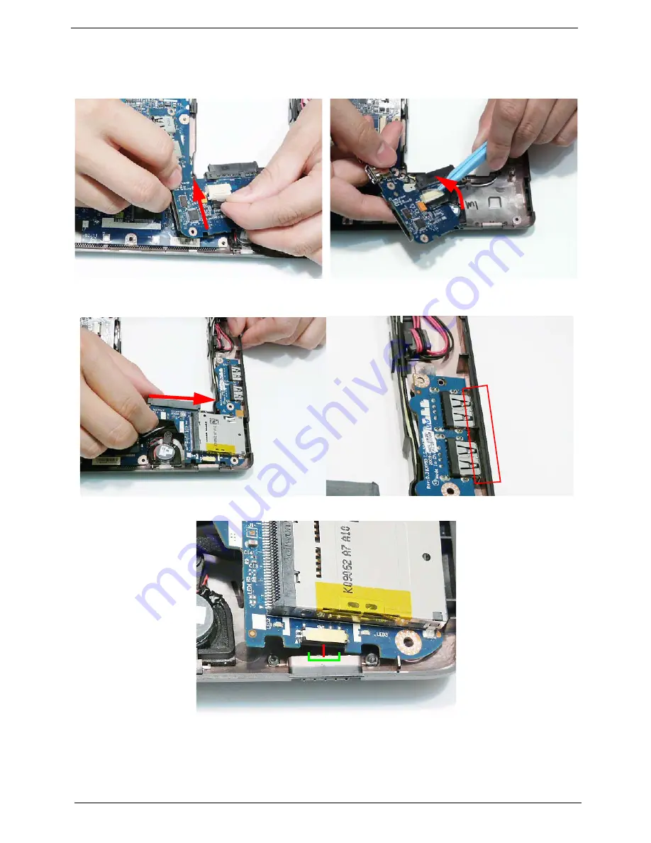
Replacing the USB Board
1.
Connect the USB cable to the connector on the
underside of the USB Board.
2.
Replace the adhesive securing the USB cable in
place.
3.
Turn the USB Board over and insert it in to the Lower Cover, right side first. Ensure that the USB ports are
accessible through the casing.
IMPORTANT:
Ensure that the Wireless Function Switch (red callout) is correctly seated in the spacer (green callout).
Summary of Contents for AOD250
Page 6: ...VI ...
Page 10: ...X Table of Contents ...
Page 28: ...18 Chapter 1 ...
Page 45: ...Chapter 2 35 3 Execute MAC BAT to write MAC information to eeprom ...
Page 46: ...36 Chapter 2 ...
Page 52: ...42 Chapter 3 4 Lift the Memory cover up to remove 5 Lift the 3G cover up to remove ...
Page 60: ...50 Chapter 3 6 Disconnect the FFC and remove the Keyboard ...
Page 70: ...60 Chapter 3 4 Remove the WLAN Board from the Mainboard ...
Page 78: ...68 Chapter 3 4 Lift the Thermal Module clear of the Mainboard ...
Page 104: ...94 Chapter 3 3 Connect the Camera cable as shown ...
Page 126: ...116 Chapter 3 4 Replace the single screw to secure the HDD in place ...
Page 155: ...Chapter 5 145 Power board Item Description SW1 Power button LED1 Power LED ...
Page 208: ...Appendix A 198 ...
Page 216: ...206 Appendix B ...
Page 218: ...208 Appendix C ...
Page 222: ...212 ...


