16
Chapter 1
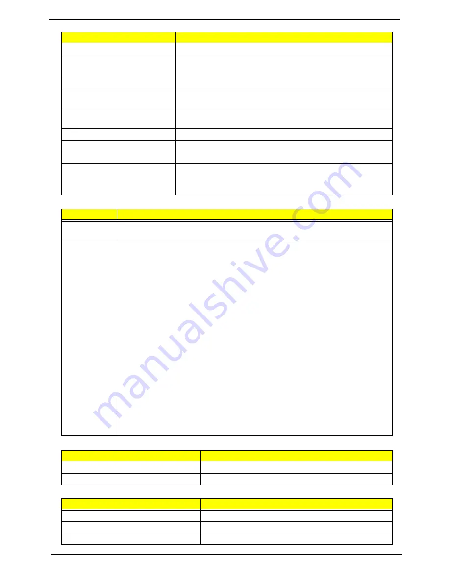
Audio Codec and Amplifier
LAN Interface
Keyboard
Pixel Pitch (mm)
0.2175
Typical White Luminance (cd/m
2
)
also called Brightness
200
Contrast Ratio
500:1
Response Time (Optical Rise
Time/Fall Time) msec
10
Typical Power Consumption
(watt)
2.5
Weight (without inverter)
180
Physical Size (mm)
235.5 x 143.5 x 5.2
Electrical Interface
LVDS
Viewing Angle (degree)
Horizontal (Right) CR = 10 (Left)
Vertical (Upper) CR = 10 (Lower)
45/45
20/45
Item
Specification
Audio
Controller
REALTEK ALC272X-GR
Features
•
Two stereo DAC support 16/20/24-bit PCM for two independent playback (multiple
streaming)
•
Two stereo ADC supports 16/20/24-bit PCM format for two independent recording
•
All DACs support independent 44.1k/48k/96k/192kHz sample rate
•
All ADCs support independent 44.1k/48k/96k/192kHz sample rate
•
Two independent SPDIF outputs support 16/20/24-bit format and 44.1k/48k/88.2k/
96k/192kHz rate
•
Supports line level mono output
•
Supports analog PCBEEP input, and features an integrated digital BEEP
generator
•
Support two stereo digital microphone input for microphone array AEC/BF
application
•
Supports legacy analog mixer architecture
•
Supports two GPIO (General Purpose Input/Output) pins (pin sharing with digital
microphone interface)
•
Supports EAPD (External Amplifier Power Down) control for external amplifier
•
Supports anti-pop mode when analog power AVDD is on and digital power is off
•
Supports 1.5V~3.3V scalable I/O for HD Audio link
•
48-pin LQFP ‘Green’ package
Item
Specification
LAN Chipset
Atheros AR8114/AR8132
Features
•
Supports 10/100
Item
Specification
Type
New Acer flat keyboard
Total number of keypads
84/88 with 101/102 key emulation
Windows logo key
Yes
Item
Specification
Summary of Contents for AOD250
Page 6: ...VI ...
Page 10: ...X Table of Contents ...
Page 28: ...18 Chapter 1 ...
Page 45: ...Chapter 2 35 3 Execute MAC BAT to write MAC information to eeprom ...
Page 46: ...36 Chapter 2 ...
Page 52: ...42 Chapter 3 4 Lift the Memory cover up to remove 5 Lift the 3G cover up to remove ...
Page 60: ...50 Chapter 3 6 Disconnect the FFC and remove the Keyboard ...
Page 70: ...60 Chapter 3 4 Remove the WLAN Board from the Mainboard ...
Page 78: ...68 Chapter 3 4 Lift the Thermal Module clear of the Mainboard ...
Page 104: ...94 Chapter 3 3 Connect the Camera cable as shown ...
Page 126: ...116 Chapter 3 4 Replace the single screw to secure the HDD in place ...
Page 155: ...Chapter 5 145 Power board Item Description SW1 Power button LED1 Power LED ...
Page 208: ...Appendix A 198 ...
Page 216: ...206 Appendix B ...
Page 218: ...208 Appendix C ...
Page 222: ...212 ...


