Chapter 3
39
External Module Disassembly Process
NOTE:
The product previews seen in the disassembly procedures may not represent the final product color or
configuration.
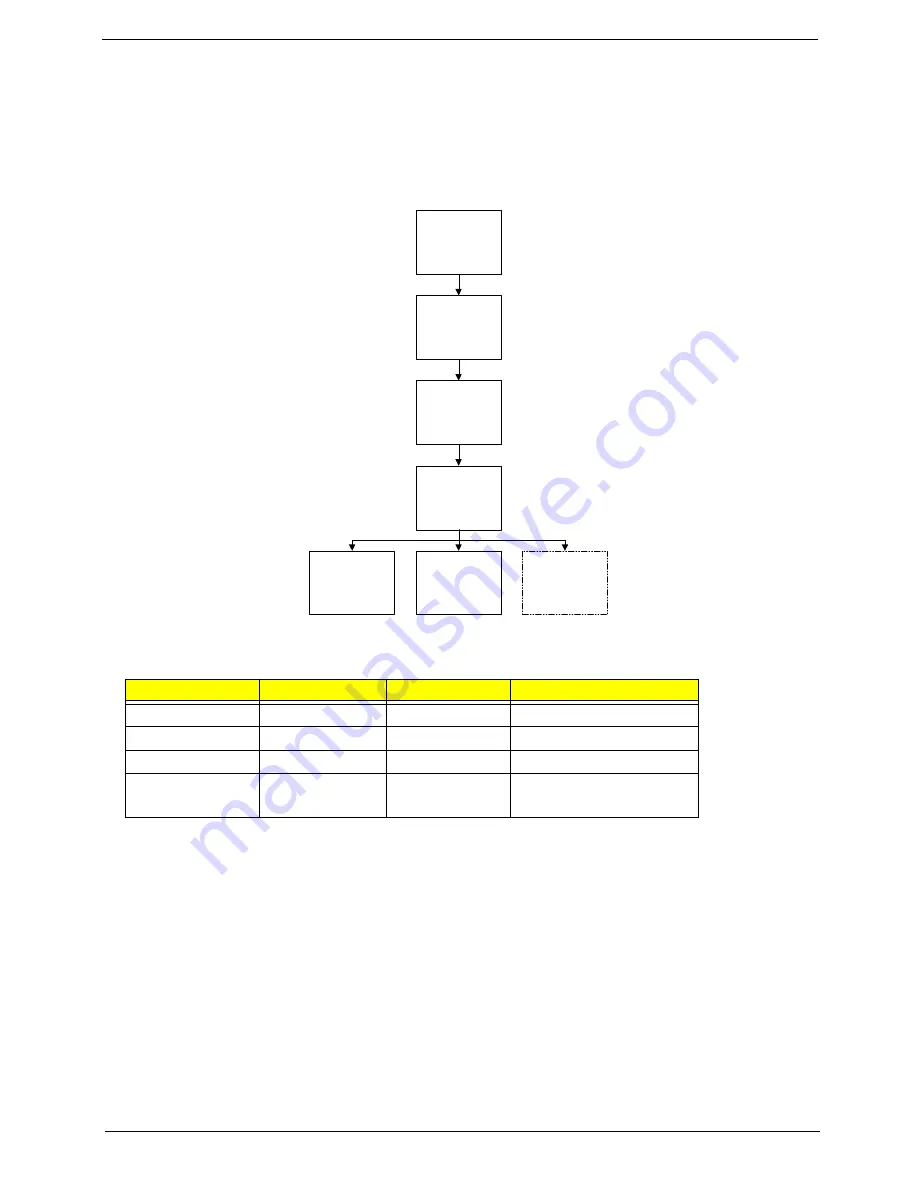
External Modules Disassembly Flowchart
NOTE:
Items enclosed with broken lines (— - - —) are optional and may not be present.
Screw List
Step
Screw
Quantity
Part No.
Lower Covers
M2*4
4
86.S6802.001
HDD Module
M2*4
1
86.S6802.001
HDD Carrier
M3*3
4
86.S6802.004
3G Module
(optional)
M2*3
1
86.S6802.003
Disconnect power
and signal cables
from system
Remove
Battery
Turn off system
and peripherals
power
Remove
DIMM
Remove
3G Module
Remove
HDD
Remove
Lower Covers
Summary of Contents for AOD250
Page 6: ...VI ...
Page 10: ...X Table of Contents ...
Page 28: ...18 Chapter 1 ...
Page 45: ...Chapter 2 35 3 Execute MAC BAT to write MAC information to eeprom ...
Page 46: ...36 Chapter 2 ...
Page 52: ...42 Chapter 3 4 Lift the Memory cover up to remove 5 Lift the 3G cover up to remove ...
Page 60: ...50 Chapter 3 6 Disconnect the FFC and remove the Keyboard ...
Page 70: ...60 Chapter 3 4 Remove the WLAN Board from the Mainboard ...
Page 78: ...68 Chapter 3 4 Lift the Thermal Module clear of the Mainboard ...
Page 104: ...94 Chapter 3 3 Connect the Camera cable as shown ...
Page 126: ...116 Chapter 3 4 Replace the single screw to secure the HDD in place ...
Page 155: ...Chapter 5 145 Power board Item Description SW1 Power button LED1 Power LED ...
Page 208: ...Appendix A 198 ...
Page 216: ...206 Appendix B ...
Page 218: ...208 Appendix C ...
Page 222: ...212 ...


