4-22
Troubleshooting
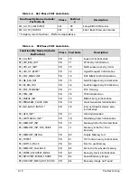
BDS_EXIT_BOOT_SERVICES*
BDS 32 Send END of POST Message to
ME via HECI
BDS_LEGACY_BOOT_EVENT
BDS
33
Last Chipset initial before
boot to Legacy OS.
BDS_ENTER_LEGACY_16_BOOT BDS
34
Ready to Boot Legacy OS.
BDS_RECOVERY_START_FLASH
BDS
35
Fast Recovery Start Flash.
* 3rd party relate functions – Platform dependence.
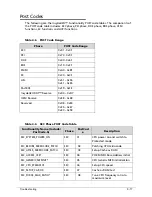
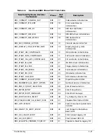
Table 4-7.
PostBDS Functions POST Code Table
Functionality Name (Include\
PostCode.h)
Phase
Post
Code
Description
POST_BDS_NO_BOOT_DEVICE
PostBDS F9
No
Boot
Device
POST_BDS_START_IMAGE
PostBDS
FB
UEFI Boot Start Image
POST_BDS_ENTER_INT19
PostBDS
FD
Legacy 16 boot entry
POST_BDS_JUMP_BOOT_SECTOR
PostBDS
FE
Try to boot with INT 19
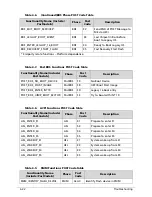
Table 4-8.
ACPI Functions POST Code Table
Functionality Name (Include\
PostCode.h)
Phase
Post
Code
Description
ASL_ENTER_S1
ASL
51
Prepare to enter S1
ASL_ENTER_S3
ASL
53
Prepare to enter S3
ASL_ENTER_S4
ASL
54
Prepare to enter S4
ASL_ENTER_S5
ASL
55
Prepare to enter S5
ASL_WAKEUP_S1 ASL
E1
System wake up from S1
ASL_WAKEUP_S3 ASL
E3
System wake up from S3
ASL_WAKEUP_S4 ASL
E4
System wake up from S4
ASL_WAKEUP_S5 ASL
E5
System wake up from S5
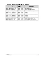
Table 4-9.
SMM Functions POST Code Table
Functionality Name
(Include\ PostCode.h)
Phase
Post
Code
Description
SMM_IDENTIFY_FLASH_DEVICE
SMM
0xA0
Identify Flash device in SMM
Table 4-6.
(Continued)BDS Phase POST Code Table
Functionality Name (Include\
PostCode.h)
Phase
Post
Code
Description
Summary of Contents for AOD257
Page 1: ...Aspire One D257 Happy 2 SERVICEGUIDE ...
Page 10: ...x ...
Page 11: ...CHAPTER 1 Hardware Specifications ...
Page 14: ...1 4 ...
Page 55: ...CHAPTER 2 System Utilities ...
Page 81: ...CHAPTER 3 Machine Maintenance Procedures ...
Page 83: ...3 3 Camera Module Installation 3 40 ...
Page 84: ...3 4 ...
Page 107: ...Machine Maintenance Procedures 3 27 ID Size Quantity Screw Type C M2 0 3 0 NI 2 ...
Page 116: ...3 36 Machine Maintenance Procedures Figure 3 33 LCD Panel ...
Page 121: ...CHAPTER 4 Troubleshooting ...
Page 127: ...Troubleshooting 4 7 9 If the issue is still not resolved refer to Online Support Information ...
Page 144: ...4 24 Troubleshooting ...
Page 145: ...CHAPTER 5 Jumper and Connector Locations ...
Page 152: ...5 8 Jumper and Connector Locations ...
Page 153: ...CHAPTER 6 FRU Field Replaceable Unit List ...
Page 154: ...6 2 Exploded Diagrams 6 4 FRU List 6 7 Screw List 6 28 ...
Page 181: ...CHAPTER 7 Model Definition and Configuration ...
Page 182: ...1 2 Aspire One D257 7 1 Aspire One Happy 2 7 109 ...
Page 388: ...7 206 Model Definition and Configuration ...
Page 389: ...CHAPTER 8 Test Compatible Components ...
Page 390: ...8 2 Microsoft Windows 7 Environment Test 8 4 ...
Page 398: ...8 10 Test Compatible Components ...
Page 399: ...Test Compatible Components 8 11 ...
Page 400: ...8 12 Test Compatible Components ...
Page 401: ...CHAPTER 9 Online Support Information ...
Page 402: ...9 2 Introduction 9 3 ...
Page 404: ...9 4 Online Support Information ...

