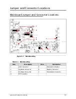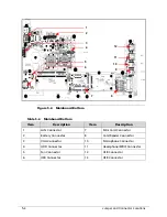
Jumper and Connector Locations
5-5
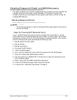
Clearing Password Check and BIOS Recovery
0
This section provides users with the standard operating procedures of clearing password
and BIOS recovery for the Aspire One D257/Happy 2. The machine provides one
Hardware Open Gap on main board for clearing password check, and one hot key for
enabling BIOS Recovery.
Clearing Password Check
0
NOTE:
NOTE
:
The following procedure is only for clearing BIOS Password (Supervisor Password
and User Password).
Steps for Clearing BIOS Password Check
0
If users set BIOS Password (Supervisor Password and/or User Password) for a security
reason, BIOS will ask the password during systems POST or when systems enter to BIOS
Setup menu. However, once it is necessary to bypass the password check, users need to
short the HW Gap to clear the password by the following steps:
1.
Remove power from the system.
2.
Remove battery.
3.
Remove lower cover.
4.
Disconnect the RTC battery
5.
Locate the CMOS jumper.
6.
Use an electric conductivity tool to short the two points of the CMOS jumper.
7.
Plug in AC, keeping the CMOS jumper shorted.
8.
Press
Power Button
until BIOS POST is finished, then remove the conductivity tool
from the CMOS jumper.
9.
Restart the system. Press
F2
to enter BIOS Setup menu.
10.
If there is no Password request, BIOS Password is cleared.
11.
If a password is requested, repeat Steps 1 through 9.
Summary of Contents for AOD257
Page 1: ...Aspire One D257 Happy 2 SERVICEGUIDE ...
Page 10: ...x ...
Page 11: ...CHAPTER 1 Hardware Specifications ...
Page 14: ...1 4 ...
Page 55: ...CHAPTER 2 System Utilities ...
Page 81: ...CHAPTER 3 Machine Maintenance Procedures ...
Page 83: ...3 3 Camera Module Installation 3 40 ...
Page 84: ...3 4 ...
Page 107: ...Machine Maintenance Procedures 3 27 ID Size Quantity Screw Type C M2 0 3 0 NI 2 ...
Page 116: ...3 36 Machine Maintenance Procedures Figure 3 33 LCD Panel ...
Page 121: ...CHAPTER 4 Troubleshooting ...
Page 127: ...Troubleshooting 4 7 9 If the issue is still not resolved refer to Online Support Information ...
Page 144: ...4 24 Troubleshooting ...
Page 145: ...CHAPTER 5 Jumper and Connector Locations ...
Page 152: ...5 8 Jumper and Connector Locations ...
Page 153: ...CHAPTER 6 FRU Field Replaceable Unit List ...
Page 154: ...6 2 Exploded Diagrams 6 4 FRU List 6 7 Screw List 6 28 ...
Page 181: ...CHAPTER 7 Model Definition and Configuration ...
Page 182: ...1 2 Aspire One D257 7 1 Aspire One Happy 2 7 109 ...
Page 388: ...7 206 Model Definition and Configuration ...
Page 389: ...CHAPTER 8 Test Compatible Components ...
Page 390: ...8 2 Microsoft Windows 7 Environment Test 8 4 ...
Page 398: ...8 10 Test Compatible Components ...
Page 399: ...Test Compatible Components 8 11 ...
Page 400: ...8 12 Test Compatible Components ...
Page 401: ...CHAPTER 9 Online Support Information ...
Page 402: ...9 2 Introduction 9 3 ...
Page 404: ...9 4 Online Support Information ...

