1-24
Hardware Specifications and Configurations
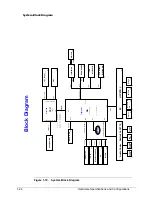
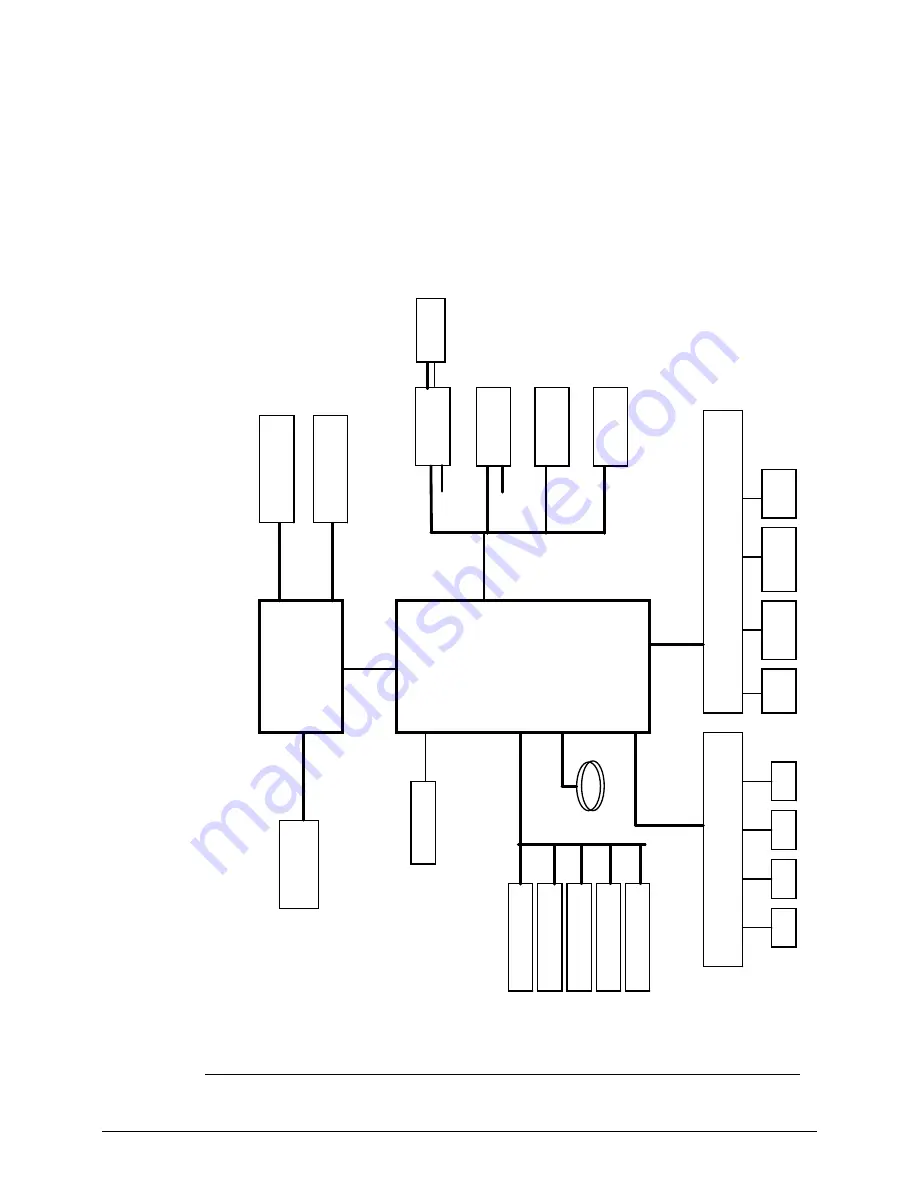
System Block Diagram
Figure 1-10. System Block Diagram
Graphic
s I
nte
rfac
es
DDR SYSTEM M
EM
ORY
PCI-E
CPU
SB
DM
I
In
te
l H
igh D
e
fi
ni
ti
on A
u
di
o
Ch
ar
g
e
r
T
ouc
h P
a
d /
B
C
on.
P
in
e
vi
ew
DM
I(x
2)
Ti
gerpoi
nt
U
S
B
2.
0 (P
ort
0
~7)
PCI-Ex
p
re
s
s
(Po
rt1
~
4
)
IN
T
_
L
V
D
S
EC
LP
C
K/
B Co
n
.
SPI
F
la
s
h
PCIE-4
PCIE-2
W
L
AN/
W
iM
A
X
US
B p
o
rt*
3
USB-0
,1
,3
SAT
A
IH
D
A
LP
C
RT
C
BA
T
T
E
R
Y
USB
DM
I
P
4
,5
,6
,7
P
8
,9
,1
0
,1
1
,1
2
,1
3
P3
P1
1
P2
2
P1
7
P2
2
P1
5
P
1
5
P2
0
P2
0
P2
4
Co
m
b
o
Jack
In
t.
SPK
CO
NN
In
t.
A
M
IC
CO
NN
A
udio Codec
P1
6
Block Diagram
SAT
A
0
S
A
T
A
- HDD
USB-2
P1
9
U
SB-5
3
G
/W
iMA
X
U
SB-7
USB-5
SI
M C
a
rd
10.
1
"P
anel
P1
4
R
ealtek A
L
C
271X
CCD
3G
P1
4
P2
0
NPCE7
9
1
L
667 M
T
/s
MI
C
Jack
Up to 1280*800 or 1366*768
D
D
R
III-
S
O
D
IMM
P2
0
N570 1.66G: AJSLBXEVT05
N475 1.83G: AJSLBX5UT08
N455 1.66G: AJSLBX9VT05
PN : AJSLGXX0T14
U
SB-4
WL
A
N
P2
0
USB-7
B
luet
oot
h m
odul
e
P1
5
USB-6
PC
IE-1
LA
N
P1
8
PCIE-3
Car
d
Read
er
P2
1
RTL8105T
A
RTS
5209-GR
P1
4
CRT
CRT
Summary of Contents for AOD257
Page 1: ...Aspire One D257 Happy 2 SERVICEGUIDE ...
Page 10: ...x ...
Page 11: ...CHAPTER 1 Hardware Specifications ...
Page 14: ...1 4 ...
Page 55: ...CHAPTER 2 System Utilities ...
Page 81: ...CHAPTER 3 Machine Maintenance Procedures ...
Page 83: ...3 3 Camera Module Installation 3 40 ...
Page 84: ...3 4 ...
Page 107: ...Machine Maintenance Procedures 3 27 ID Size Quantity Screw Type C M2 0 3 0 NI 2 ...
Page 116: ...3 36 Machine Maintenance Procedures Figure 3 33 LCD Panel ...
Page 121: ...CHAPTER 4 Troubleshooting ...
Page 127: ...Troubleshooting 4 7 9 If the issue is still not resolved refer to Online Support Information ...
Page 144: ...4 24 Troubleshooting ...
Page 145: ...CHAPTER 5 Jumper and Connector Locations ...
Page 152: ...5 8 Jumper and Connector Locations ...
Page 153: ...CHAPTER 6 FRU Field Replaceable Unit List ...
Page 154: ...6 2 Exploded Diagrams 6 4 FRU List 6 7 Screw List 6 28 ...
Page 181: ...CHAPTER 7 Model Definition and Configuration ...
Page 182: ...1 2 Aspire One D257 7 1 Aspire One Happy 2 7 109 ...
Page 388: ...7 206 Model Definition and Configuration ...
Page 389: ...CHAPTER 8 Test Compatible Components ...
Page 390: ...8 2 Microsoft Windows 7 Environment Test 8 4 ...
Page 398: ...8 10 Test Compatible Components ...
Page 399: ...Test Compatible Components 8 11 ...
Page 400: ...8 12 Test Compatible Components ...
Page 401: ...CHAPTER 9 Online Support Information ...
Page 402: ...9 2 Introduction 9 3 ...
Page 404: ...9 4 Online Support Information ...

