Hardware Specifications and Configurations
1-43
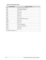
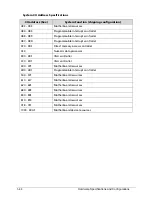
System IO Address Map
I/O address (hex)
System Function (shipping configuration)
000 - 01F
Direct memory access controller
020 - 021
Programmable interrupt controller
024 - 025
Programmable interrupt controller
028 - 029
Programmable interrupt controller
02C - 02D
Programmable interrupt controller
02E - 02F
Motherboard resources
030 - 031
Programmable interrupt controller
034 - 035
Programmable interrupt controller
038 - 039
Programmable interrupt controller
03C - 03D
Programmable interrupt controller
040 - 043
System timer
04E - 04F
Motherboard resources
050 - 053
System timer
060
Standard PS/2 Keyboard
061 Motherboard
resources
062
Microsoft ACPI-Compliant Embedded controller
063 Motherboard
resources
064
Standard PS/2 Keyboard
065 Motherboard
resources
066
Microsoft ACPI-Compliant Embedded controller
067
Motherboard resources
070 - 073
System CMOS/real time clock
074 - 07F
Motherboard resources
080 Motherboard
resources
081 - 091
Direct memory access controller
092 Motherboard
resources
093 - 09F
Direct memory access controller
0A0 - 0A1
Programmable interrupt controller
0A4 - 0A5
Programmable interrupt controller
0A8 - 0A9
Programmable interrupt controller
0AC - 0AD
Programmable interrupt controller
0B0 - 0B1
Programmable interrupt controller
Summary of Contents for AOD257
Page 1: ...Aspire One D257 Happy 2 SERVICEGUIDE ...
Page 10: ...x ...
Page 11: ...CHAPTER 1 Hardware Specifications ...
Page 14: ...1 4 ...
Page 55: ...CHAPTER 2 System Utilities ...
Page 81: ...CHAPTER 3 Machine Maintenance Procedures ...
Page 83: ...3 3 Camera Module Installation 3 40 ...
Page 84: ...3 4 ...
Page 107: ...Machine Maintenance Procedures 3 27 ID Size Quantity Screw Type C M2 0 3 0 NI 2 ...
Page 116: ...3 36 Machine Maintenance Procedures Figure 3 33 LCD Panel ...
Page 121: ...CHAPTER 4 Troubleshooting ...
Page 127: ...Troubleshooting 4 7 9 If the issue is still not resolved refer to Online Support Information ...
Page 144: ...4 24 Troubleshooting ...
Page 145: ...CHAPTER 5 Jumper and Connector Locations ...
Page 152: ...5 8 Jumper and Connector Locations ...
Page 153: ...CHAPTER 6 FRU Field Replaceable Unit List ...
Page 154: ...6 2 Exploded Diagrams 6 4 FRU List 6 7 Screw List 6 28 ...
Page 181: ...CHAPTER 7 Model Definition and Configuration ...
Page 182: ...1 2 Aspire One D257 7 1 Aspire One Happy 2 7 109 ...
Page 388: ...7 206 Model Definition and Configuration ...
Page 389: ...CHAPTER 8 Test Compatible Components ...
Page 390: ...8 2 Microsoft Windows 7 Environment Test 8 4 ...
Page 398: ...8 10 Test Compatible Components ...
Page 399: ...Test Compatible Components 8 11 ...
Page 400: ...8 12 Test Compatible Components ...
Page 401: ...CHAPTER 9 Online Support Information ...
Page 402: ...9 2 Introduction 9 3 ...
Page 404: ...9 4 Online Support Information ...


