3-6
Machine Maintenance Procedures
Maintenance Flowchart
0
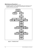
The flowchart in Figure 3-1 shows a graphic representation of the module removal and
installation sequences. It shows information on what components may need to be
removed and installed during servicing.
Figure 3-1.
Maintenance Flow
SD Dummy
Card
Battery
Keyboard
Base Cover
HDD module
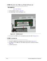
DIMM Module
WLAN
Module
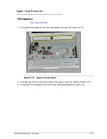
Upper Case
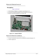
Bluetooth
module
Mainboard
Speakers
LCD Module
Thermal
Module
LCD Bezel
Microphone
LCD Hinge
LCD Panel
LVDS Cable
Camera
Summary of Contents for AOD257
Page 1: ...Aspire One D257 Happy 2 SERVICEGUIDE ...
Page 10: ...x ...
Page 11: ...CHAPTER 1 Hardware Specifications ...
Page 14: ...1 4 ...
Page 55: ...CHAPTER 2 System Utilities ...
Page 81: ...CHAPTER 3 Machine Maintenance Procedures ...
Page 83: ...3 3 Camera Module Installation 3 40 ...
Page 84: ...3 4 ...
Page 107: ...Machine Maintenance Procedures 3 27 ID Size Quantity Screw Type C M2 0 3 0 NI 2 ...
Page 116: ...3 36 Machine Maintenance Procedures Figure 3 33 LCD Panel ...
Page 121: ...CHAPTER 4 Troubleshooting ...
Page 127: ...Troubleshooting 4 7 9 If the issue is still not resolved refer to Online Support Information ...
Page 144: ...4 24 Troubleshooting ...
Page 145: ...CHAPTER 5 Jumper and Connector Locations ...
Page 152: ...5 8 Jumper and Connector Locations ...
Page 153: ...CHAPTER 6 FRU Field Replaceable Unit List ...
Page 154: ...6 2 Exploded Diagrams 6 4 FRU List 6 7 Screw List 6 28 ...
Page 181: ...CHAPTER 7 Model Definition and Configuration ...
Page 182: ...1 2 Aspire One D257 7 1 Aspire One Happy 2 7 109 ...
Page 388: ...7 206 Model Definition and Configuration ...
Page 389: ...CHAPTER 8 Test Compatible Components ...
Page 390: ...8 2 Microsoft Windows 7 Environment Test 8 4 ...
Page 398: ...8 10 Test Compatible Components ...
Page 399: ...Test Compatible Components 8 11 ...
Page 400: ...8 12 Test Compatible Components ...
Page 401: ...CHAPTER 9 Online Support Information ...
Page 402: ...9 2 Introduction 9 3 ...
Page 404: ...9 4 Online Support Information ...

