3 System upgrades
50
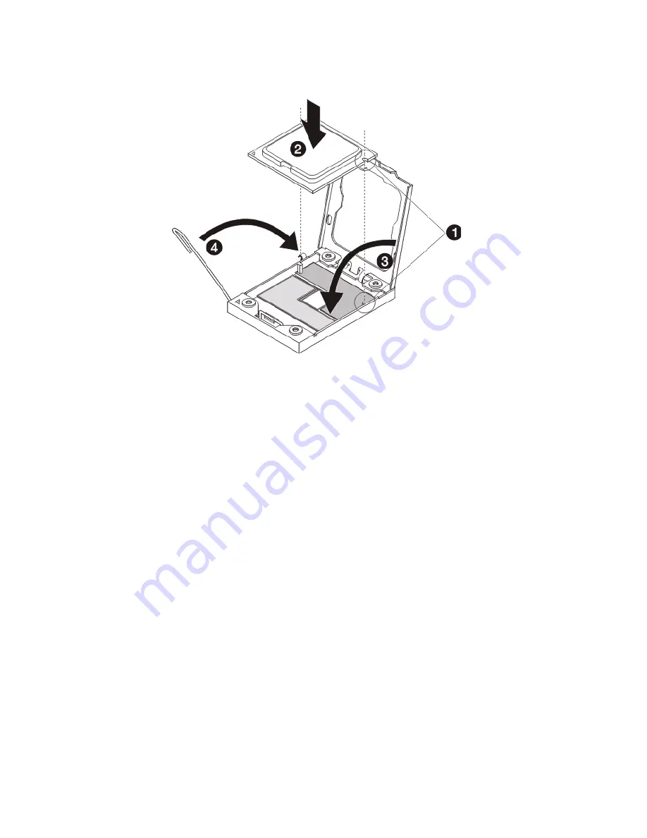
(4) Engage the load lever back into place.
9
Apply the thermal interface material.
(1) Use an alcohol pad to wipe off the old thermal grease
from both the heat sink and the processor socket
retention plate.
(2) Apply a thin layer of an approved thermal interface
material before installing the heat sink.
Make sure that only a very thin layer is applied so that
both contact surfaces are still visible.
10 Install the heatsink (see “Installing a heatsink” on page page 46).
11 Observe the post-installation instructions described on page page
28.
12 Repeat the steps above to replace the second processor.
Summary of Contents for AR360 F1 Series
Page 1: ...AR360 F1 Series User Guide ...
Page 16: ...xvi ...
Page 17: ...1 System tour ...
Page 32: ...1 System tour 16 ...
Page 33: ...2 System setup ...
Page 40: ...2 System setup 24 ...
Page 41: ...3 System upgrades ...
Page 42: ...3 System upgrades 26 ...
Page 80: ...3 System upgrades 64 2 Insert the riser into the mainboard 1 and fasten the two 2 screws 2 ...
Page 84: ...3 System upgrades 68 The figure below shows the server in a rack mount position ...
Page 92: ...3 System upgrades 76 ...
Page 93: ...4 System BIOS ...
Page 130: ...4 System BIOS 114 ...
Page 131: ...5 System troubleshooting ...
Page 141: ...Appendix A Server management tools ...
Page 146: ...Appendix A Server management tools 130 ...
Page 147: ...Appendix B Rack mount configuration ...
Page 157: ...Appendix C Acer Smart Console ...
Page 186: ...Appendix C Acer Smart Console 170 ...


